The heart rate, also referred to as pulse rate, has been recognized as a vital sign since the beginning of medicine, and it is directly related to a person’s cadiovascular health. Today, we are going to make a PC-based heart rate monitor system using an Arduino board and Easy Pulse V1.1 sensor. Easy Pulse is a pulse detecting sensor that uses the principle of transmission photo-plethysmography (PPG) to sense the pulse signal from a finger tip. The sensor output is read by the Arduino board, which then transfers the data to the PC through a serial interface. A PC application is developed using Processing programming language to display the received PPG signal and instantaneous heart rate.
Brief introduction of Easy Pulse V1.1
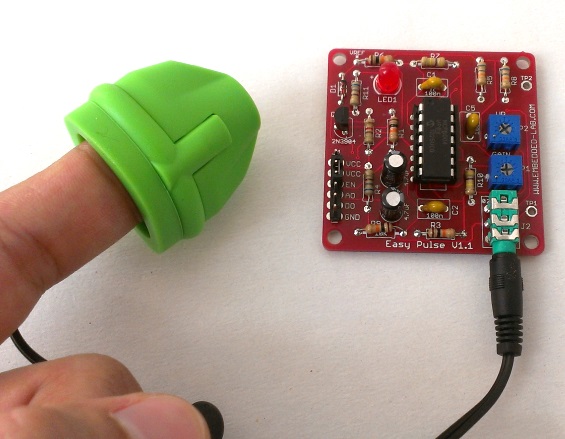
The Easy Pulse sensor is designed for hobby and educational applications to illustrate the principle of photoplethysmography (PPG) as a non-invasive optical technique for detecting cardio-vascular pulse wave from a fingertip. It uses an infrared light source to illuminate the finger on one side, and a photodetector placed on the other side measures the small variations in the transmitted light intensity. The variations in the photodetector signal are related to changes in blood volume inside the tissue. The signal is filtered and amplified to obtain a nice and clean PPG waveform, which is synchronous with the heart beat. For more details, read Easy Pulse V1.1.
Hardware setup
The hardware setup for this project is very simple. All you need is an Easy Pulse V1.1 sensor, an Arduino board, a PC, and few wires. The analog PPG output from Easy Pulse board is fed to an ADC channel of Arduino to convert it into digital counts for further processing. In this project, I am using a Crowduino board, a clone of Arduino Duemilanove, which is manufactured by Elecrow.
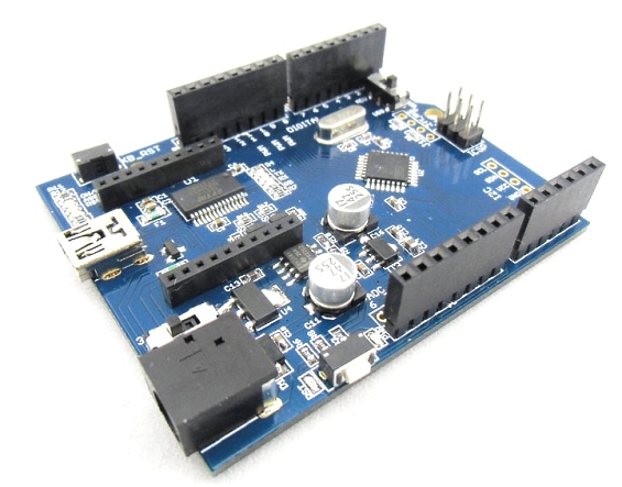
The Crowduino is 100% compatible with Arduino Duemilanuve and comes with additional features. The major difference between Crowduino and other arduino compatible boards is the Crowduino contains a XBee socket. Thus Crowduino not only can adapt all the shields that are compatible with arduino Uno, but also adapts to the Xbee modules from Digi, and any module with the same footprint.
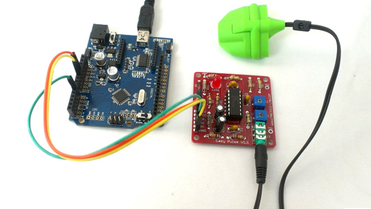
The following picture shows the connections between the Easy Pulse, Crowduino and Power supply. The Easy Pulse sensor operates at +5V. The Enable pin (EN) of Easy Pulse is tied to VCC pin so that the sensor is activated. There is a 2-pin jumper on the Easy Pulse board to do this. The jumper is placed between VCC and EN pin by default, so you don’t need an external wire to do this. The analog output pin (AO) goes to analog input channel A0 of Crowduino. A mini USB cable connects the Crowduino board to the PC. The power supply for Easy Pulse is derived from the Crowduino board.