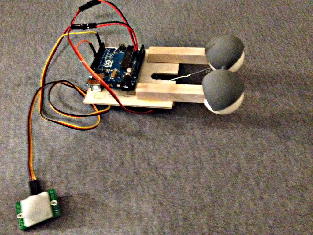
Someone had seen Peter Penguin or my Instructables on Animatronic Penguin Torso or Animatronic Eyes, and was working on a sculpture. He wanted to animate the sculpture when someone walked into the room and asked if I could do it. I thought about it for a while. There were several differences from my penguin, (no laptop controlling the action, could use an SSC-32 as I had before, but may be overkill, and I had never used a PIR Motion Detector before.) But after researching Arduinos and the motion detector from Roboshop ( http://www.robotshop.com/en/parallax-pir-motion-sensor.html ), decided to have a go.
SO this is Mark II of my Animatronic Eyes. The eyes do not rotate, but that wasn’t requested. It would not be too difficult to add that feature back in, now that I have this model functional.
For more information, go to www.djsfantasi.com OH, and if you like this, please vote for my ‘ible in the contest (the button is in the upper right!!)
Step 1: Tools
- Small screwdrivers
- Drill (drill press preferred, also pin vise and portable drill)
- Cutoff Saw, razor saw, jigsaw or razor knife
- Hobby knife
- Pliers, cutoff pliers
- sandpaper
- Circle Template
- Dial Caliper (Digital if you’re so lucky)
- Soldering iron
- Masking tape
Step 2: Materials
- 12”x12” 3mm Birch plywood
- 12” ½”x ½” bass stripwood
- Easter eggs (small)
- Ping Pong balls (standard)
- Lg. paper clips
- Arduino Uno kit (including Wall Wart and USB connector)
- Micro Servo, 9g Heavy Duty
- Servo 24” extension cable
- Misc. 3x male headers (from misc. Servo extension cables)
- Misc. 2 pin female header to 2 pin female header, preferable with black and red wires. Recovered from junk PC.
- Electrical Shrink tubing.
- Wood glue
- Epoxy
Step 3: Planning
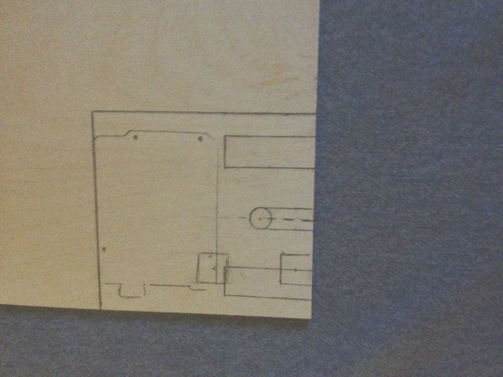
Success in a project like this is planning, planning, planning. I foresaw four separate stages. Design of the base, the eye mechanism, the linkage and the code.
- Base to hold Arduino, servo and eyes. I had designed eyes before, but this one had new challenges, It was to be buried in a rock sculpture and its skin was several inches thick. It also only had to blink. That allowed me to use a long support bar for the eyes and pivot on the eyeballs themselves. SketchUp 8 allowed me to visualize the base designs in 3D.
- Mechanism for eyes. The ideas presented above then dictated the design of the eye mechanism
- Linkage specifically for eyes. This tool helped me immensely – linkage mechanism designer and simulator. It allowed me to simulate the linkage between the servo and eyelid mechanism, and determine the lengths of material required. Basically, the servo arm, moves a long linkage, which in turn, rotates the T linkage thus opening and closing the eyelids.
- Control code. I saw this as the easiest portion of the effort, as I am a coder from way back. I have supplied the code for your benefit in the Instructable..
Step 4: Assembling the eyes
The support bar is two lengths of 4” x ½” x ½” bass stripwood from Michael’s.
Holes are needed on the Ping Pong balls for the support bar and the pivot rod. Marking holes for support bar and pivot holes, I use the joint line as a circumference, and draw an 11/16” circle centered on the circumference. Place the hole on a piece of sandpaper and rotate to smooth out the edges.
Then, at 90 degrees to that hole, drill a hole on the circumference with the diameter of the selected sprue bar used for the T when making the eyelids (a good reason to read ahead, when trying to follow directions). I use a circle template for determining size, circumference, angles and position on the ping pong balls.
Place the ping pong balls on support bars through the large hole. The end of the support bar should be coated in epoxy. Ensure that the pivot holes are in line. What to do when pivot holes are not in line?
Well, if you did as I did, when I placed the ping pong balls on the support bars, I eyeballed the 90 degrees for the pivot holes. I was wrong. Or, I did a sloppy job drilling the hole at 90 degrees in the first place. In that case, I should have used an L at 90 degrees to mark the position of the two holes. In the latter case, I should have used a scrap piece of sprue rod to align everything up. I usually mock up most of what I build anyway (see last picture). Never eyeball a measurement if you can possibly avoid it. Use that High School math and get it right.
But it was bollixed now. So, I marked where one of the pivot holes SHOULD have gone and with increasing drill bits, drilled it out. It still was too close to the bad, bad hole – so I filled up the hole with more epoxy and redrilled it once again. Now as I write this, I realize that the OTHER side was available for a second attempt and I could have used it.
You may need to spray the eyes white, depending on the ping pong ball used. In mine, the epoxy color bled through
Step 5: Making the Eyelids
Find a piece of plastic model sprue, in a T shape. The head of the T should be 1-¼” long, and the handle of the T should be ¾”. Mark the head of the T, 3/8” from the center in both directions. This is where the eyelids will stop. Heat a thick paper clip with a lighter and GENTLY melt a hole through the leg of the T, at the 6/10″ mark.
Select two matched ROUND plastic Easter egg tops. Note that when separated each half has a distinct shape. Choose the most perfectly round halves you can get.
Mark the egg vertically, approximately 3/10” from center. I did this by eye, holding the egg and ping pong ball together to see where the cut should be made. Use the above as a starting point. Cut off at this line (I used a cutoff saw, CAREFULLY – those eggs are slippery. Once the excess has been trimmed off, place the cut edge on a piece of sandpaper and sand the edge smooth. The edge that connects to the other egg half also has to be trimmed off. This can be done with the cutoff pliers and sanded as in the other edge.
The eye assemblies were placed in a wood clamp, 1.735” apart at the sides, ¾ ” apart between the eyeballs, and the pivot holes were carefully aligned. (This is where I discovered that I had a problem, and had to punt and go back to the previous step).
The eyelid (cut Easter egg) will have to be drilled to press fit the sprue selected for the T. In two opposing corners of the eyelid, drill the holes there. First, place the eyelid on an eyeball and mark where the pivot will go.Then with the two eyelids together, mark the second eyelid. If you have trouble visualizing this, place the trimmed eyelids on the workbench, side by side, so the opening faces you. The two adjacent corners will be where the pivot holes will be drilled. Mark the second also with a permanent marker (which on the eggs is not so permanent) It is best drilled on a drill press.These eggs are made of some plastic from the outer universe, more slippery than Teflon.
Next, we’ll glue the assembly together. I have a picture of the various adhesives I tried to glue to the eggs. Only epoxy worked, and even then not all epoxies worked. I used LocTite 1 minute epoxy, but be warned – I had bad luck with the instant mix kind and ended up manually mixing the epoxy like I would have. More on this step later.
Step 6: Making the eyelids – Part II
Hand assemble the eyes (in the wood clamp) and the eyelids. The support bars should be parallel and 1.73″ apart. The distance between the eyeballs should be 3/4″.
You may have to loosen one of the eyes to bend it out to get the pivot bar to fit. Ensure the edges of the eyelids are at the 3/8” mark you made earlier; the handle of the T should be centered. Now, get a couple scraps of masking tape, and from the top, hand position the eyelids into the closed position and keep them there with the tape.
The leg of the T should be approximately 27 – 30 degrees from the plane of the eyelid back. The Linkage design shows this much larger, 55 degrees, but it practice as I assembled the eyelids, I found this position to work.
Bend a paper clip into a pointer. Mix up some epoxy. With the bent paper clip as an applicator, run a bead around the T and the eyelid, both sides. Let it set (they advertise 1 minute; I give it 5). Once it has set, disassemble the sub-assembly and run a bead around the bottom of the joint with another batch of epoxy. Let it harden thoroughly.
Once the servo has hardened overnight, spray paint the eyelid, either gray or black.
Step 7: Assembling the Base – Servo
Every component and their mounting surfaces, should be marked out on the plywood base. Piece fitting was done before anything was glued or attached.
The first pieces should be ½” x ½” x ½” cubes used to mount the micro servo and they should be glued and clamped to the base. The micro servo is screwed into these pieces, after they have had the glue cure and pilot holes drilled into them.
I had to cut off one corner of the mounting blocks, as the servo cable exited at a back corner. You can see this in one of the pictures.
For more detail: New animatronic Eyes: Rock On!