many cases switches are just switches. They directly control the flow of electricity to an appliance, flashlight or mains-voltage lamp. An example of this is the switch on the wall in your living room. In many cases nowadays however, switches are digital sensors, meaning that instead of directly controlling a high-powered device, they are controlling a logic (low power) signal to a microcontroller (eg Arduino), telling the microcontroller which state a user prefers, High or LOW, On or Off, 1 or 0 (they all amount to the same thing).
We don’t often think about switches as sensors, chiefly because they are older technology, with which we are completely familiar. Nevertheless, a switch can always be used as a digital sensor, transmitting one bit of information, which is whether the switch state is Off or On (which can also be defined as 0 & 1).
This wiki entry focuses on momentary switches but it is important to note that many other types of switches, such as toggle switches or slide switches, can be wired in exactly the same manner and used as digital sensors, with the same code examples as used below.
The schematic symbols for switches can vary somewhat. The symbol for S2 is more descriptive of a breadboard-mounted momentary switch but the basic idea is exactly the same, a connection is being created by pushing the switch.
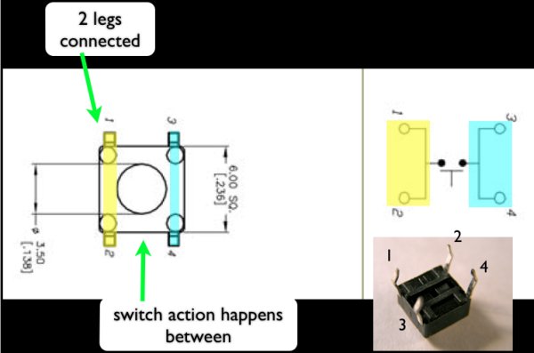
The are a couple of confusing things to consider in using momentary switches. One aspect is that the switch has four leads but only two wires are actually being switched (if you check the schematic symbol). The switching action happens between the leads spaced at the shortest distance. The other two leads are connected internally along the “longer” side of the switch. The middle diagram above shows the idea. You can easily prove out which leads are shorted, if you forget, but using your mulitmeter on the continuity setting (aka “beep setting”).
Why do I need a pulldown or pullup resistor?
Students often have a hard time grasping why we need a pulldown or pullup resistor on a switch. One way of explaining this is in describing the nature of the Arduino pin when it is set to INPUT. The pin is described as being in a “high-impedance state”. This means that it requires very little current to switch the pin from HIGH to LOW or vice versa. Without a pullup or pulldown, the input pin can be thought of as “flapping in the wind” and any small amount of charge is capable of flipping the pin’s state. This charge could come from any capacitive field (all conductors act as capacitors to some extent). Often an Input pin which is left “floating” will capacitively couple to nearby pins and follow them.
The purpose of a pullup or pulldown is to steer a pin into a known state, until the switch is actuated, or an input in sensed. The pullup or pulldown resistor, banishes this “flapping in the wind” and gives the input a known behavior.
Different ways of wiring a switch
There are three different ways of wiring a switch (on an Arduino pin) with a pullup or pulldown resistor.
- A switch may be wired with an external pulldown resistor
- A switch may be wired with an external pullup resistor
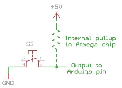
- A switch may use the internal pullup resistors in the Atmega chip
For more detail: Momentary Switch as Digital Sensor