I wanted an in-circuit ESR meter (equivalent series resistance meter) to aid in determining the condition of electrolytic capacitors without the need of desoldering them first. When capacitors fail you will often have some signs of failure such as bulging of the capacitor top. Starting in approximately 2002 and continuing till about 2010 there was a glut of high failure rate capacitors on the market which found their way into everyday items such as PC power supplies, monitors, motherboards etc. These devices would test fine after manufacturer and continue to work for the consumer for many years but fail prematurely, often in as little as one year.
I purchased a MESR-100 Meter from eBay for around $55 USD shipped to my door in Winnipeg (Canada). The meter came well packaged in a retail box, this is a nice change from many other items from China that are simply wrapped in bubble wrap and stuffed into a padded envelope. Inside the box was the meter, two short meter leads and a manual. Pressing the red power button for a few seconds powers the meter, it is ready to use after about 3 seconds. The display is a backlit LCD display, it does appear that the backlight is on all the time. The display is nice and bright and has a good viewing angle, there are two hot spots near the bottom of the display which is probably due to the location of the backlight LEDs but it doesn’t effect display readability.
The meter has 3 modes, autoranging, 0 to 1 ohm, 1 to 10 ohm and 10 to 100 ohm. The modes can be cycled through by pressing the mode range button. The meter can be zero calibrated by shorting the leads and pressing the zero button. All of the buttons need to be pressed for about half a second before they are recognized, a quick tap isn’t usually sufficient. This button sensitivity could be improved but other than powering the unit on I am thinking it will live in automatic mode until it is switched off after use anyway.
The display has lots of useful information. There is a battery indication, mode indication, large resistance reading and some smart text under the reading that indicates some criteria of when the capacitor under test would be considered good. There is also a chart on front of the meter but the automatic text output during the reading is very convenient.
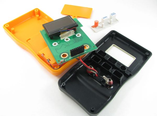
The meter is powered by a PIC18F24K20 microcontroller, there are also some unpopulated areas which suggests that there might be a more advanced version of this meter available. The other main IC on the board is a TI LMV824 Precision Low Voltage Operational Amplifier. The case also has some indications of a second version, directly under the 3 existing buttons you can see a space for 3 more, it is obvious from the inside of the case and is also slightly visible when looking at the front of the meter.
The meter case could be improved, it is cheap feeling and the tilting bail works but feels like it will break in time with normal use. The display protection is quite thin and you can feel it deform easily with a light press. The cutout on the side for the external USB jack is not centered very well adding to the low quality look and feel of the case. I wouldn’t have this thing unprotected in a toolbox since the case would be prone to damage in that scenario.
The PCB is of high quality, it is a single side SMD loaded board. The PCB has an immersion gold finish which should keep it corrosion free for a long time. The solder joints look good, there is some hand soldering of the leads that run to the battery compartment and the front test jacks, these could have been soldered better but they are adequate, it was nice to see some heavy wire going to the banana jacks on the front but their placement made it cumbersome to re-assemble the meter since the plugable area is between where the leads are soldered into the board and the jack, this means you need to bend the wires around the plugable area while reassembly. There is one bodge on the board, it looks like a lower profile capacitor was originally specified but when it was manufactured the capacitor that was used was slightly too tall so it was soldered in and allowed to lay against the PCB for clearance. You can see it in the pictures below and in the video.
The reading are believable but I don’t have any other test equipment on hand that can confirm if the ESR readings are accurate, the manual does indicate that the meter is accurate to 1% and 2% depending on the range you are in. The meter states that it uses a 100KHz frequency to test the capacitors using a sign wave and this was confirmed on the scope, the test voltage is around 150mV.
Overall I am pleased with the meter, for the price the functionality. If you are looking for a meter in this price range I would recommend it.
For more detail: MESR-100 ESR meter review and teardown