One fine day, I was weighing my self on a weighing scale. Suddenly a thought came to my mind, ‘How much would be the mass of Earth?’. Leave that apart ‘How can we even measure it?’. There is no such weighing scale on which, Earth can be placed. There has to be some indirect way to measure mass of the Earth. Here I present implementation of one such indirect method to measure mass of the Earth.
Step 1: The Indirect Method
In early nineteenth century scientists used Newton’s second law and Newton’s law of universal gravitation to measure mass of the Earth. These equations are F = ma and F=(GmM)/(r2) respectively(m=mass of the object, a=acceleration, G=Gravitational Constant, M=mass of the Earth, r=Radius of the earth). If we substitute g i.e. acceleration due to gravity for the ‘a’ acceleration term and combine these two equation we get.
mg = GmM/r2
This equation can be solved for M i.e mass of the earth.
M = (gr2)/G.
We will assume that we know the value of G and r. We will find g i.e. acceleration due to gravity using a small experiment, involving arduino and a few sensors. Finally we will put all things together to find the value of M.
If equations seems a bit awkward , look at the attached image.
Let’s get started with the experiment.
Step 2: Things We Will Need
Here is the list of things we will need for experiment to measure acceleration due to gravity.
- Any arduino board, preferably uno/duomilanove (no specific reason just that I have used this board for this experiment)
- USB cable for connecting arduino to PC
- 560 Ohm resistors (4 in quantity), 100 Ohm resistors (2 in quantity)
- piezoelectric sensor (4 in quantity)
- One pair of IR Tx (IR LED) and Rx(Photodiode)
- One potentiometer
- One opamp (like UA741C)
- One breadoard
- Three 1.2 meter long wires
- small 5cmx5cm general purpose PCB for assembling IR circuitry
- Tape
- Cardboard sheet
In case of any doubt look at the attached Images.
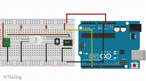
Step 3: Schematic 1: the IR Circuitary
This circuit will be used to time-stamp the starting time of free fall for an object used to measure ‘g’. Here are the important points about the fritzing schematic image.