Connecting the Switch
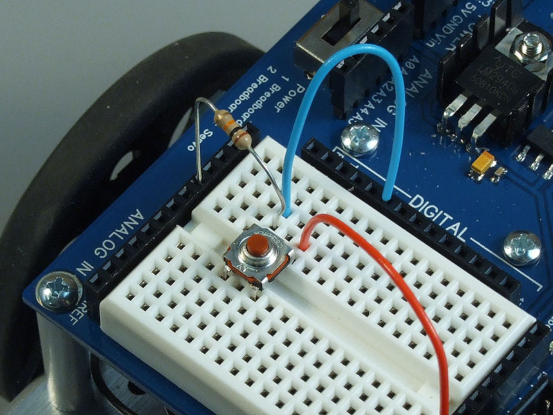
To connect the switch to the Arduino, you will need the switch, two jumper wires, and a 10kΩ (brown-black-orange) resistor.
Once you have all the required parts, you will need to wire the switch to the Arduino using the breadboard.
NOTE: The virtual board may be slightly different from the physical one. This is because of some limitations of the program used to create the virtual layout. Both the physical and virtual layout will work the same way.
Configuring ROBOTC
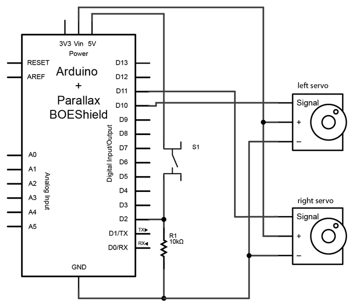
Now that we have everything connected, we need to tell ROBOTC how to configure the pins before we can program. We need to tell ROBOTC that we are using the Parallax BOE Shield, and that we have the drive servos connected to pins 10 and 11. We also need to tell ROBOTC that pin 2 is a digital input (the start switch) and name it “startSwitch”.
- Parallax Boe Shield
- Continuous Rotation Servo named “leftServo” on pin 10
- reversed Continuous Rotation Servo named “rightServo” on pin 11
- Digital High Impedance named “startSwitch” on pin 2
Once that is done you should have the following at the top of your source code file.
#pragma config(CircuitBoardType, typeCktBoardUNO)
#pragma config(PluginCircuitBoard, typeShieldParallaxBoeBot)
#pragma config(UART_Usage, UART0, uartSystemCommPort, baudRate200000, IOPins, dgtl1, dgtl0)
#pragma config(Sensor, dgtl2,  startSwitch, sensorDigitalHighImpedance)
#pragma config(Motor, servo_10, LeftServo, tmotorServoContinuousRotation, openLoop, IOPins, dgtl10, None)
#pragma config(Motor, servo_11, RightServo, tmotorServoContinuousRotation, openLoop, reversed, IOPins, dgtl11, None)
//*!!Code automatically generated by 'ROBOTC' configuration wizard               !!*//
Programming
For this project we just want to demonstrate how the switch can be used to start a program. To keep it simple, we will just have the robot drive forwards, backwards, and stop. Since we already have code to drive forwards and backwards, we will just copy that code into the current file and modify it.
task main()
{

  while(true) //repeat indefinitely
  {
    // code to drive forward for 2 seconds
    motor[leftServo] = 20;   //Set the left servo to go forward at power level 20
    motor[rightServo] = 20;  //Set the right servo to go forward at power level 20
    wait1Msec(2000);         //pause code execution for 2000ms (2 seconds)

    // code to stop the robot for 1 second
    motor[leftServo] = 0;    //Set the left servo stop
    motor[rightServo] = 0;   //Set the right servo stop
    wait1Msec(1000);         //pause code execution for 1000ms (1 second)

    // code to drive backwards for 2 seconds
    motor[leftServo] = -20;  //Set the left servo to go backwards at power level -20 (absolute power of 20)
    motor[rightServo] = -20; //Set the right servo to go backwards at power level -20 (absolute power of 20)
    wait1Msec(2000);         //pause code execution for 2000ms (2 seconds)

    // code to stop the robot for 1 second
    motor[leftServo] = 0;    //Set the left servo stop
    motor[rightServo] = 0;   //Set the right servo stop
    wait1Msec(1000);         //pause code execution for 1000ms (1 second)
  }
}
To read the status of the switch we use the command
For more detail: Making a program start using a switch