Creating a robotics platform from scratch takes allot of work and a few dollars. Buying a ready built one is easy but costs allot of money (at least for me). So instead I decided to piggy back off of the companies who make remote control cars.
This is a great because it comes ready made with two h-bridges and a steering mechanism already built. The cost of the whole project is probably $90 if you don’t have any of the materials but for me I was about $3(for the batteries).
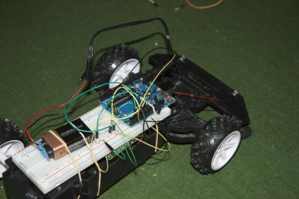
This test shows how the robot works. I didn’t have a large enough space to test it while it moved. And I also had it running the dark seeking sketch.
Because i’m entering this in the robot contest I’d like to say i’m 13-18 years old and belong to the 401 venture company (scouts).
Materials:
1x Arduino (I used an Uno but any will do)
1 x Breadboard
1 x 9v Battery
1 x 9v to Arduino cable (link to make your own)
1 x Arduino to USB cable
1 x R.C Car
2 x LEDs (hopefully the same)
3 x AA batteries (for the car)
About 50cm of four strand wire
15 – 20 jumper wires
A few elastics
Some electrical tape
Some solder (lead free)
Tools:
Soldering iron
Wire strippers
Small screwdrivers
Third Hand (for soldering)
Computer (with Arduino software installed)
Step 2: Taking Apart the Car
The first thing that we need to do is take the body of the car. Depending on which car you have you may require some strange screwdrivers. Luckily mine came with standard screws. Also depending on the car you may have to cut off the antenna don’t worry we don’t need it for this project (remember to keep it as it comes in handy latter).
Next we need to take the screw out of the PCB (Printed Circuit Board) so that we can more easily access the brain of the car.
Step 3: Figuring Out The Chip
In order to replace the car’s on board chip with the Arduino we must first find out what each pin on the on board chip controls. To do this Google the name and number of your chip (most cars use this one).If you can’t find a diagram online you can manually find out what each pin does using this guide.
Once the use of each pin is known we can remove the chip (if yours doesn’t have a diagram draw your own or label the chip). I found that because I don’t have a solder braid trying to remove the chip was tricky. The best way I found was to thread the antenna of the car (or similar piece of thin wire) under one pin, then melt the solder and pull up on both ends of the antenna. However the important thing is that you get the chip out.
Step 4: Basic Movement
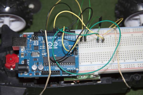
The first thing that we need to do is solder a piece of wire (10 – 15 cm) to the holes in the PCB that control left, right, forward, backward, and ground (or negative). Once that is done connect the negative wire to ground on your breadboard and then from ground on the breadboard to the gnd pin on the Arduino. Next connect the forwards wire (directly or through the breadboard) to pin 7 on the Arduino. The others follow the same method
Left to pin 2 right to pin 4 and backward to pin 8
THE CODE
This sketch will test out each of the car’s basic movements if your car fails to perform any of the actions double check all connections and ensure that it is connected to the right pin on the PCB and on the Arduino.
Basic Movements Sketch: copy and paste or download the file at the bottom of the page and open it with Arduino.exe
int left = 2; // left connected to pin 2
int right = 4; // right connected to pin 4
int forward = 7; //forward to pin 7
int backward = 8; // backward to pin 8
void setup() // happens only once when the Arduino is turned on
{
// setting all the pins to outputs
pinMode (left,OUTPUT);
pinMode (right,OUTPUT);
pinMode (forward,OUTPUT);
pinMode (backward,OUTPUT);
}
// creating functions so we don’t have to type as much
void go_forward() {
digitalWrite (forward,HIGH);
digitalWrite (backward,LOW);
}
void go_backward() {
digitalWrite (backward,HIGH);
digitalWrite (forward,LOW);
}
void go_left() {
digitalWrite ( left,HIGH);
digitalWrite (right,LOW);
void go_right () {
digitalWrite (right,HIGH);
digitalWrite (left,LOW);
}
void go_stop() { // could’t use just stop because it’s taken
digitalWrite (right,LOW);
digitalWrite (left,LOW);
digitalWrite (forward,LOW);
digitalWrite (backward,LOW);
}
void loop() { // runs over and over again until Arduino is turned off
go_forward();
delay (1000); // car goes forward for one second
go_backward();
delay (1000); // then goes backwards for a second
go_right();
go_forward();
delay (1000); // car will make a right turn for a second
go_left();
go_forward();
delay (1000); //car will make a left turn for a second
go_stop();
delay(1000); // car will stop for a second
}
STOP COPYING HERE
For more detail: Light Seeking R.C Car Hack (with Arduino)