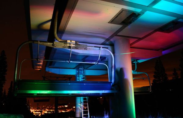
Today I’m going to show you how I made my “light painters palette” aka light box. If your into electronics and photography than this is probably something you are going to like.
Supplies:
-Arduino (I’m using a arduino pro mini which requires a ftdi basic to program, But an uno or leaonardo… would work just fine)
–Tri Color LED Breakout Kit
–Rocker Switch
-A Battery Holder for 4 AA‘s
-2 Toggle Switches
-2 10k Resistors
-3 10k Potentiometers
-3 Knobs (Red, Green, and Blue)
–IR Receiver (Almost any 38 kHz variety will work)
-IR Remote, mine came from a LED strip that burnt out. But any NEC remote works with some software adjustments (You could just buy one of these, have to check the remote codes)
-Enclosure of some sort, I used this one
-Some hookup wire
-4 little nut and bolt combo’s that fit the Tri-Color LED Kit board
-LED bevel (doesn’t even really fit the IR receiver, but oh well)
Building Supplies:
Drill and an assortment of bits
Soldering Iron
Flux and Solder
Wire cutters and strippers
Dremmel tool or jewelers saw
Double sided tape
Step 1: Hardware
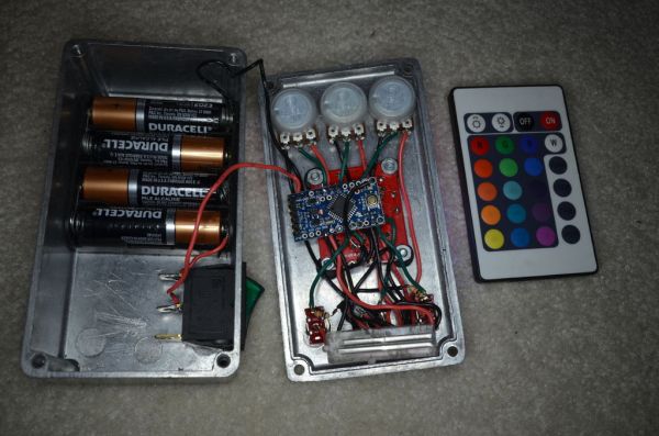
To build it just drill a bunch of holes in the lid to your enclosure, mount the parts with their included hardware. Be careful not to space the potentiometers to close or they might not fit, my was too close for comfort. I mean that was totally planned. I’d suggest orienting the microcontroller so the analog inputs are on the side of the potentiometers, and the digital inputs are on the side of the switches. Use the double sided tape to secure the battery holder to the bottom of the enclosure. The power switch seemed to fit nice on the side. Give enough wire between the battery and power switch to the lid so you can open it easily. I also tried to make sure to wire the components through the bottom of the Arduino so if I needed to probe around I had some room. I used a spare piece of protoboard for a power and ground rail, however that’s not necessary. You could just solder a huge ball of wire ends together. Flash the microcontroller with the software I’ve got here, drop in some batteries, close up the lid and your done!
The Potentiometers have three solder points, one side to 5V, one side to Gnd, the center to an analog input. If the sides are backwards then just flip the last two values in the mapping function after the analogRead functions in the software. This will reverse the clockwise vs counter-clockwise brightening/dimming relationship. I’d suggest a clockwise turn makes the LED’s brighter.
The switches are SPDT, so one side goes to 5V, one side has a wire to the digital input and a 10K to Gnd. The 10k is a pulldown resistor which just makes sure the switch stays in determinate state all the time.
The IR Receiver has 5V, GND and Data lines from right to left (check your data sheet to be sure, I’ve burnt a couple of these for sure). The data line can connect to any digital input pin.
The LED’s breakout kit has a 5V, Gnd, and data lines for each of the three colors. Be sure to wire these to a PWM pin, maybe not pin 5 and or 6 because I think they mess with the delay function and you might not be able to turn that LED all the way off. What ever is closest to the mounting spot.
The batteries get wired to the Raw and Gnd inputs. Send the positive lead through the power switch first.
Make sure however you wire it that it matches the software parameters!!
For more detail: Light Painters Palette aka Light Box