This instructable is meant to be a more complete explanation than others available online. Notably, this will provide more hardware explanation than is available in the LED Marquee instructable by led555.
Goals
This instructable presents the concepts involved with shift registers and high side drivers. By illustrating these concepts with an 8×8 LED matrix I hope to provide you with the tools needed to adapt and expand to the size and layout your project calls for.
Experience and Skills
I would rate this project to be of medium difficulty:
- If you already have experience programming microcontrollers and working with LEDs this project should be fairly easy for you to complete and to scale to larger arrays of lights.
- If you are just starting out with microcontrollers and have flashed an LED or two you should be able to complete this project with some help from our friend google.
- If you have little or no experience with microcontrollers or programming this is probably beyond what you should be getting yourself into. Try out a few other beginner projects and come back when you’ve got some more experience writing programs for microcontrollers.
Disclaimer and Credit
First, I am not an electrical engineer. If you see something that is wrong, or not a best practice, please let me know and I’ll make the correction.
Do this at your own risk! You should know what you’re doing or you can cause damage to your computer, your microcontroller, and even yourself.
I have learned a lot from the internet, particularly from the forums at: http://www.avrfreaks.net
I am using a font set that came with the ks0108 universal C library. Check that out here:
http://en.radzio.dxp.pl/ks0108/
Step 1: Parts
Parts List
General Parts
To make an 8×8 grid of LEDs and control them you will need:
- 64 LEDs of your choice
- 8 Resistors for the LEDs
- 1 Shift register for the columns
- 1 Driver array for the rows
- 8 Resistors for switching the driver array
- 1 microcontroller
- 1 clock source for microcontroller
- 1 prototyping board
- 1 power supply
- Hook-up wire
Specific Parts Used Here
For this instructable I used the following:
- 64 green LEDs (Mouser part #604-WP7113GD)
- 8 220ohm 1/4 watt resistors for the LEDs (Mouser part #660-CFS1/4CT52R221J)
- 1 HEF4794 LED driver with shift register (Mouser part #771-HEF4794BPN)
- 1 mic2981 High-Voltage High-Current Source Driver Array (Digikey part #576-1158-ND)
- 8 3.3kohm 1/4 watt resistors for switching the driver array (Radio Shack part #271-1328)
- 1 Atmel ATmega8 microcontroller (Mouser part #556-ATMEGA8-16PU)
- 1 12MHz crystal for the microcontroller clock source (Mouser part #815-AB-12-B2)
- 1 2200-hole prototyping board (Radio Shack part #276-147)
- Converted ATX power supply: See This Instructable
- Solid core 22-awg hook-up wire (Radio Shack part #278-1221)
- Solderless breadboard (Radio Shack part #276-169 (no longer available, try: 276-002)
- AVR Dragon (Mouser part #556-ATAVRDRAGON)
- Dragon Rider 500 by Ecros Technologies: See This Instructable
Notes Regarding Parts
Row and Column Drivers: Probably the most difficult part of this project is picking the row and column drivers. First off, I do not think a standard 74HC595 shift register is a good idea here because they cannot handle the kind of current we want to send through the LEDs. This is why I chose the HEF4794 driver as it can easily sink the current present when all 8 leds are in one row are switched on.
The shift register is present on the low side (the ground pin of the leds). We will need a row driver that can source enough current to string multiple columns together. The mic2981 can supply up to 500mA. The only other part I have found that performs this task is the UDN2981 (digikey part #620-1120-ND) which is the same part by a different manufacturer. Please send me a message if you know of other high-side drivers that would work well in this application.
LED Matrix: This matrix is 8×8 because the row and column drivers each have 8 pins. A larger LED array may be built by stringing multiple matrices together and will be discussed in the “modular concepts” step. If you want a large array, order all of the needed parts at one time.
There are 8×8, 5×7 and 5×8 LED matrices available in one convenient package. These should be easy to substitute for a diy matrix. Ebay is a good source for these. Mouser has some 5×7 units available such as part #604-TA12-11GWA. I used cheap green LEDs because I’m just playing around and have fun. Spending more on high-brightness, high-efficiency LEDs can allow you to produce a much more spectacular looking display… this is good enough for me though!
Control Hardware: The matrix is controlled by an Atmel AVR microcontroller. You will need a programmer for this. Because I am prototyping I am using the Dragon Rider 500 for which I have written both assembly and usage instructables. This is an easy tool for prototyping and I highly recommend it.
Step 2: The matrix
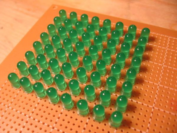
I will be building my own LED matrix for this project using 5mm leds and a prototyping board from Radio Shack. It should be noted that you can purchase 8×8 dot matrix led modules from several sources, including ebay. They should work just fine with this instructable.
Construction Considerations
Alignment
The LEDS need to be aligned so they face the same direction at the same angle. I found the easiest option for me was to put the body of the LED flush to the board and hold it there with a small piece of plexiglass and a clamp. I put a few LEDs in place a couple of inches away from the row I was working on to make sure the plexiglass was parallel with the prototyping board.
Rows and Columns
We need to have a common connection for each row as well as each column. Because of our row and column driver choice we need to have the anode (positive lead of the LED) connected by row and the cathode (negative lead of the LED) connected by column.
Control Wires
For this prototype I am using solid core (single conductor) hook-up wire. This will be very easy to interface with a solderless breadboard. Feel free to use a different connector type to suit your project.
Building the Matrix
1. Place the first column of LEDS in the prototyping board.
2. Double check that your polarity for each LED is correct, this will be very difficult to fix if you realize it later.
3. Solder both leads of the LED to the board. Check to make sure they are aligned correctly (not at weird angles) and clip off the cathode leads. Make sure you do not clip the anode lead, we will need that later so just leave it pointing up.
4. Remove the insulation from a piece of solid core wire. Solder this piece of wire to each cathode right at board level.
- I tacked this at each end then went back and added a bit of solder at each junction.
- This wire should run past your last LED to make for an easy interface when we add control wires.
5. Repeat parts 1-4 until you have all LEDs in place and all column buses soldered.
6. To create a row bus, bend several of the anode leads at a 90 degree angle so they touch the other anode leads in the same row.
- There are detailed pictures of this below.
- Take care not to let these come in contact with the column buses, creating a short circuit.
7. Solder the leads at each junction and clip off the excess anode leads.
- Leave the last anode sticking past the final LED. This will be used to connect the row driver control wires.
8. Repeat parts 6 & 7 until all rows buses have been soldered.
9. Attach control wires.
- I used red solid core wire for the rows and black for the columns.
- Connect one wire for each column and one for each row. This can easily be done at the end of each bus.
Important
This LED matrix does not have any current limiting resistors. If you test this without resistors you will probably burn out your LEDs and all this work will be for nothing.
Step 3: The control hardware
We need to control the columns and the rows of our LED matrix. The matrix has been constructed so that the Anodes (voltage side of the LED) constitute the rows, and the Cathodes (ground side of the LED) make up the columns. This means our row driver need to source current and our column driver needs to sink it.
In order to save on pins I am using a shift register to control the columns. This way I can control an almost unlimited number of columns with just four microcontroller pins. It is possible to use only three if the Enable Output pin is tied directly to voltage. I have selected the HEF4794 LED driver with shift register. This is a better option than a standard 74HC595 as it can easily sink the current present when all 8 LEDs are on at one time.
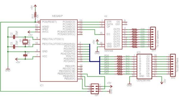
On the high side (current source for the rows) I am using an mic2981. The schematic shows a UDN2981, I believe these two are interchangeable. This driver can source up to 500mA of current. Because we are only driving 1 row at a time this gives a lot of opportunity for expansion, up to 33 columns for this chip (more on that in the “modular concepts” step).
Building the Control Hardware
For this instructable I have just breadboarded this circuit. For a more permanent solution you will want to either etch your own circuit board or use prototyping board.
1. Row Driver
- Place the mic2981 (or UDN2981) in the breadboard
- Connect Pin 9 to Voltage (This is confusing in the schematic)
- Connect Pin 10 to Ground (This is confusing in the schematic)
- insert 3k3 resistors connecting to pins 1-8
- Connect from Port D of the ATmega8 (PD0-PD8) to the 8 resistors
- Connect the 8 row control wires of the LED matrix to pins 11-18 (note that I have connected the lowest row of LEDs to Pin 18 and the Highest row to Pin 11).
2. Column Driver
- Place the hef4794 in the breadboard
- Connect Pin 16 to voltage
- Connect Pin 8 to ground
- Connect 220 ohm resistors to Pins 4-7 and 11-14.
- Connect the 8 column control wires from the LED matrix to the 8 resistors you just connected.
- Connect Pin1 (Latch) to PC0 of the ATmega8
- Connect Pin2 (Data) to PC1 of the ATmega8
- Connect Pin3 (Clock) to PC2 of the ATmega8
- Connect Pin15 (Enable Output) to PC3 of the ATmega8
3. Clock Crystal
- Connect a 12MHz crystal and load capacitors as shown in the schematic
4. ISP
- Connect the programming header as shown in the schematic
5. Filtering Capacitor and Pull-up resistor
- It is best to filter the voltage supplied to the ATmega8. Use a 0.1uf capacitor between Pin 7 & 8 of the ATmega8
- The reset pin should not be left floating as it can cause random resets. Use a resistor to connect it to voltage, anything about 1k should be good. I’ve used a 10k resistor in the schematic.
6. Make sure you are using +5v regulated power. It’s up to you to design the regulator.
For more detail: LED matrix using shift registers