As the nights gradually lengthened in autumn 2011, I discovered the joys of Arduino and thought that it would be a great way to implement something that I have wanted for a long while – a gentle way to wake up on a winter’s morning. Sadly, it has taken me over a year to find the time and understanding to put it all together, but here, in time for some of the shortest days of this winter, are the results!
The idea is that getting up when it’s pitch-black is a wrench. Equally, having a timed light that just switches on all of a sudden is a shock. What you want is a gentle ramp of light from imperceptibly dim to ragingly bright and ideally going from a nice gentle red to blazing white so that your brain thinks it’s time to start that melatonin level rising. My solution is a full-function micro-controller, RTC alarm-clock with the following features, among others:
Arduino compatible ATMega328 controlled, open, hackable, reprogrammable.
Battery backed-up RTC
Brightness-controllable red LED display
Cool rotary encoder input
Up to 18W LED dawn light
8-channel PWM light control (2 x 3W RGB + 2 x 6 x 1W white)
Exponential brightness ramp on dawn light
7 independent dawn alarms stored permanently in EEPROM
Alarms setable for any day, for every day, for mon-fri or for sat-sun.
One-press “arm/disarm” with indicator (stored in battery-backed RTC RAM)
Each alarm has optional buzzer
Escalating buzzer tone
Snooze function on buzzer
Controllable “ramp” time (min to max brightness time)
Controllable “hold” time (time at max brightness)
Controllable “buzzer delay” (time between max brightness and buzzer)
Easily controlled “Night Light”
“Security Light” mode (mode stored in RTC battery-backed RAM so safe to blackouts etc).
A dawn clock aims to wake you up gently and you can buy them commercially, but they are expensive, generally just white, not very flexible, and just not much fun! We’ll aim to make a full-feature dawn alarm clock and add a buzzer too, just to be sure we actually get to work on time! It’s also something of a learning exercise for me so it has a whole bunch of different interface and control techniques for me (and perhaps you) to master along the way. There’s about 6 separate projects in here and I’ll try to put some example code in so that you can try them separately if you wish.Although you could do this project perfectly well on a “real” Arduino, and indeed it was prototyped with a “nano” on a breadboard, I’m making the dedicated installation on a minimal Ardu’ compatible so that you don’t need to commit your “real” Ardu’ to the clock. I have made this project both on bits of perf-board and on a dedicated PCB that I have designed & had fab’d. We’ll look at both ways to do it – the result is much the same but the PCB is much less time consuming.There are several discrete “sub-projects” that I’ve called “modules” in this project, any of which could be made and used individually:
The Arduino clone & RTC
The Digital time display
The Rotary encoder & switch controls with de-bounce.
The “Shift PWM” LED driver board
The lamps themselves & a trivial “buzzer” alarm.
Controlling an ATX power supply for efficient powering of the device
I’ve tried to make this instructable modular so just skip over any modules you can handle yourself already or use just one or two parts for your own project.
 Remove these ads by Signing Up
Step 1: See it Working – plus some Shameless Groveling
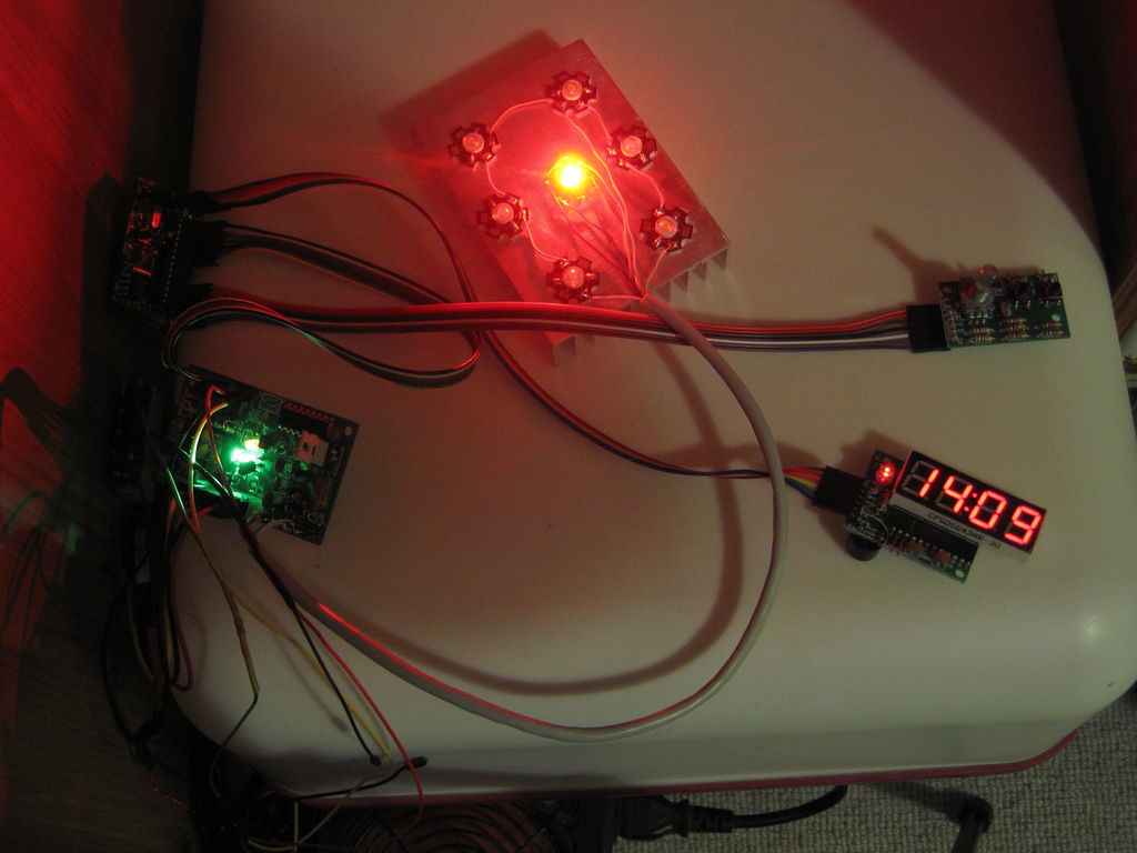
This is the finished and functional clock in action – the alarm is set to come on at 14:40 (if I could get up at that time I wouldn’t need this clock!) and I have set it to ramp up over 1 minute (normally you would use 10-30mins but it makes a rather dull video). You will see that every few seconds the lamp gets brighter. The ramp-up and colours aren’t very good in the video but you get the idea. At the end of the ramp-up, the lamp stays on but the alarm sounds (you might normally have a delay but again, it makes a rather dull video). I press to snooze the alarm, and then again to cancel the light and reset.
Shameless Groveling:
I’ve entered this ‘ible into the “Glow” contest so if you like it or any of its modules then please consider voting for it. I could have split it into a few entries but really it’s more sensible all together and it’s taken a year to get together. So if you like it, please….
Vote for me and help me get me some more fun stuff to make fun instructables with!
Cheers
Ugi
Step 2: Materials
This is the approx BoM for the clock I made. It’s by no means optimised and many of the items are simply what I had to hand or could source easily from ebay. However, it does seem to work.
1 ATmega328 -DIP
1 16 MHz Crystal
1 Max7219 – DIP
1 74HC595 – DIP
8 AMC7135 – SMD 350mA
1 DS1307 – DIP
1 32.768 KHz watch crystal
2 IRF540N MOSFET*
6 BCU81 low voltage NPN
12 White 1 W LED on star
2 3W RGB LED on star
2 Heat Sink for 12W LED
1 4-digit red 7-seg display (12 pin, common cathode)
1 Rotary encoder & knob (5-pin with press-switch)
1 CR2032 3V Li Battery
1 Holder for CR2032
1 custom PCB or 4+ small perf boards
1 Heat sink glue
1 ATX power supply
1 ATX motherboard extension cable
3 Momentary/tactile switches
1 Tactile switch
1 5V Buzzer
18 100 nF ceramic capacitor
2 orange 3mm LEDS
2 green 3mm LEDs
1 red 5mm LED (flat top)
15 1K
9 10K
6 Male header pins x 7**
3 Male header pins x 6**
1 Male header pin x 3**
5 Male header pins x 2**
1 Male header pin x 1**
1 Strip of female header (useful but not essential)
1 x 40-way splittable F-F ribbon cable with individual F ends
1 Molex Socket (reclaimed or bought)
2 22 pF Ceramic cap
3 100uF Electrolytic Cap
1 470uF Electrolytic Cap
1 1000uF Electrolytic Cap
10 1N4001 (or simiar) rectifier diodes (1A, 0.8v forward voltage).
60-80cm (2-3 feet) 4-pair solid copper network cable or similar
Linkup wire (I tended to use wire from an old 3-pair telecom cable).
The relevant items are pictured by module – we’ll come back to the BoM for each module as we go along.
Nearly everything was sourced from cheap Chinese suppliers on e-bay, either for this project or for others and left over. I didn’t attempt to optimise it and I often bought more than I needed to have useful spares in my bits box. The last step has some additional info including what I paid. Some of the prices are more than a year old now, however. Your mileage may vary.
Tools:
Solder station
Solder
Heatshrink
Helping hands
Clippers
Pliers
File
Bench vice
Craft knife
Heat source for heatshrink (lighter)
USB to TTL converter (CP2102 based – less than £2 delivered from e-bay)
PC with Arduino IDE
Arduino for bootloading (unless your ‘328 is already bootloaded)
* This is massive over-kill for the current we are switching in this project but it was in-hand and I needed a low on-resistance because of the specific white LEDs I had bought.
** You may not want all of these header pins and you may want some straight and some 90’ headers. Have a look at the later steps and see what they are all for.
Step 3: PCB – layout & preparation
Throughout this instructable I have described two ways in which you can construct this project – using hand-wiring on little perf-boards and also using a custom PCB. There are more photos of some of the PCB steps because the perf-board version was more or a prototype. This step describes designing the PCB. If you’re not interested in that method then just skip this step.
The PCB Eagle files* (schematic and board) are attached to this step and if you have a reasonably priced way of having them fab’ed then I strongly recommend that approach. It takes a fraction of the time and the result is much neater. There were a few minor errors in the original PCBs that I had made up but those were easily sorted and are all corrected in the attached version. I am pretty sure this version is fully functional without any messing about.
The project is in several modules and so it should really have at least 4 separate PCBs. Unfortunately, that works out pretty expensive. As a result, I designed all four modules on a single 79 x 99 mm PCB. That is as large as you can design in the freeware version of Eagle and can be fab’ed for a reasonable price as one piece. It is designed to work as a single piece but where each section joins there are pairs of header pins so that the modules can be broken apart and re-joined with jumpers.
Note: The sub-boards are separated by lots of little holes. Not all fab’ shops allow that – check before you buy.
I used sitopway.com, who fab’ed this board for $40 + $15 postage to UK. It came in about 10 days.
If you have the perforated PCB fab’ed then it will work as a single unit but you will probably prefer to separate it into four pieces and re-join them with jumper wires. I did this by placing the PCB in a vice at the break-point, scoring along the join (to cut the tracks that join the parts) with a craft knofe on both sides and just whacking it with the heel of my hand. It snaps cleanly without damaging the tracks.
As you see from the pictures, you first need to snap longways along the long perforation, then snap each part into two. That should give you:
A controller/RTC board (top left)
A clock display board (top right)
A switch & encoder board (bottom left)
An LED driver board (bottom right)
In the next few steps we’ll populate each of these boards in turn, look at what they can do and test the functions of each.
* There were a few small errors in the version I had fab’ed – nothing that wasn’t fixable. I have corrected these in the attached files and I think they are 100% correct. However, I have not tested the final version. Please check the files yourself before you pay to have them fab’ed!
 Dawn Clock Board 6 Fixed v2.sch1 MB
Step 4: Module 1 – The Arduino / RTC module – Overview
The heart of this device is an Arduino compatible ATmega328. You could use a “genuine” Ardu’ board and something like a prototyping shield for the RTC & connections but by making our own little board we can put all the pins we need together, include some of the pull-down resistors etc and put the 1307 RTC with its battery backup right next to the ‘328 on the same little PCB or perf-board. We don’t need a regulator or a USB connection for this project so the part-count and cost is pretty low.
You could use this module or a variant of it for any time-based application. We break out nearly all of the useful pins to male headers and it can be re-programed by serial on the board. You will need a USB to TTL cable for programming the alarm-clock code or test code (or indeed for your own code). Mine is called “CP2102” based and was £4.75 for two including delivery (e-bay). They are even cheaper now.
To program by serial connection you need a ‘328 with the “Duemilanove” bootloader. You can buy these chips pre-programmed with the bootloader or use an ISP programmer. I used an existing Arduino as ISP with my new chip on a breadboard according to this tutorial:
http://arduino.cc/en/Tutorial/ArduinoToBreadboard
However, what that doesn’t tell you is that you need to disable the auto-reset so look here:
http://www.arduino.cc/playground/Code/MegaISP
for the solution to that. I used a 100Ohm and 10 Ohm resistor in series from the reset pin to +5V. A 100uF capacitor between them works equally well.
If, like me, you get a ‘328-PU rather than a 328P (I didn’t know the difference but apparently they have different power-saving modes) then you may find that the bootloader won’t load because these two chips have a different device signature and the software that actually talks to the programmer (AVRdude) gets confused. The quickest fix for this is to find your avrdude.conf file and in the entry under ATmega328, edit the line:
signature = 0x1e 0x95 0x0F;
to read:
signature = 0x1e 0x95 0x14;
That makes AVRdude look for a ‘328-PU and all is well. Change the .conf file back after (once the bootloader is programmed). The bootloaded ‘328-PU will program from the IDE by serial with no problem and behaves exactly like a normal Arduino.
The ATMega328 Datasheet is at: http://www.atmel.com/Images/doc8161.pdf just in case you need 448 pages of light reading!
You will also see that I have rather gone to town on the capacitors on this board (and indeed this project). Perhaps because of the heavy PWM of several amps of LEDs, I was finding this clock was a bit unstable and would sometimes stall. Also the display went a bit mad occasionally. I have therefore taken the approach of adding a 100nf to each power connection of each chip, a 100uF on each board and a massive 470-1000uF on the Ardu’ board and driver board. It’s probably over-kill but it seems to work. Use your judgment as to what to leave out if you have a better understanding of these things than me.
As a final note, I have included female headers to take temporary LEDs on the power line and on pin 13. We are using pin 13 for communication and I didn’t really want it flickering away all night. With a header I can pug in the LED when I want to test something and then take it out again after. If you want a permanent LED on pin 13 just solder it in place of the female headers.
BoM for Module 1:
1 PCB or Perf Board (X by Y holes)
1 28-pin DIN socket (optional but advisable)
1 bootloaded ATmega 328
1 16MHz crystal
2 22 pf ceramic capacitors
1 1307 RTC**
1 32.768 KHz, 12.5 pF watch crystal
1 2032 battery holder
1 2032 3V lithium battery (not pictured)
1 tactile switch (6×6 mm)
3 100 nf ceramic capacitors
3 10K resistors*
2 1K resistors
1 orange 3mm LED
1 green 3mm LED
optional – 2 x 2pin female header.
1 1000 uf electrolytic cap (not pictured)
2 x 7 pin male header (straight or 90′)
2 x 6 pin male header (straight or 90′)
1 x 2 pin straight male header
link-up wire if using perf-board (I used some old 3-pair phone cable). I will assume this in all further modules.
*according to the datasheet,** the RTC should probably have 2.5K pullups but 10K seems to work fine.
** http://www.sparkfun.com/datasheets/Components/DS1307.pdf
Step 5: Module 1 – Arduino / RTC Module – wiring
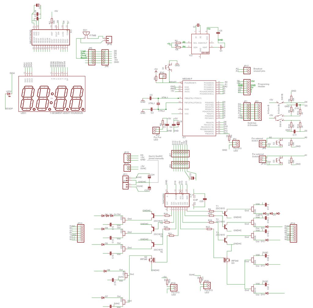
The first picture here is a schematic for this module. I drew that before I got the hang of any “proper” schematic drawing tools so it may not be very polished but I actually think you can see what’s connected to what comparatively well. I have laid the schematic out in a similar pattern to the board so it should be fairly clear how that translates to the actual soldering work.
The Eagle schematic is the second picture. If it’s too small to read you should be able to download it at the original resolution. Alternatively, the Schematic and Board files are attached.
The third picture shows the Arduino, RTC, Display and input modules all on a breadboard based around an Arduino nano. It’s possible, but pretty messy!
For the PCB version:
In general it’s easier to start soldering from the middle outwards. However, you need to do some of the top side components before the battery-holder because it covers the solder pads for many of these. Some of this is a little fiddly so it might not make the best first-project but nothing on this module is terribly difficult. As always, put the components through their holes, bend leads or pins out a little to hold them, turn the board over, solder and clip off.
My order was:
R6 (1K), 2-pin header for A2/A3, 1-pin header for reset.
Reset tactile switch, 10K pullup resistor on reset and neighbouring 100nf capacitors.
28-pin DIP (try to get the notch the right way around)
DS1307 RTC chip
Battery holder on the back
Crystals and 22pf caps
R2/R3 10K pullups for I2C communication (notionally these should be 2.5k)
Two x 2-pin female headers for power & D13 LEDs, plus other 1k resistor
Final 100nf cap, and remaining male headers all the way around.
1000uf cap under the board,
Cut down some 3mm LEDs to go in the female headers
Insert the bootloaded ‘328 (get the notch at the right end)
Add the RTC battery to the holder & off you go!
For Perf-board version:
My approach was:
1 – lay out the key components leaving some space for the large extras like the battery holder and that massive 1000 uf capacitor. The RTC uses pins 27 and 28 of the ‘328 so I put it up in that corner (you’ll see it’s upside down in comparison with the ‘328).
2 – solder down all of the major parts including the chips and header pins. Include as many of the key capacitors etc. as close to the chips as we can. The watch crystal I put in the same holes as pins 1 & 2 of the ‘1307.
3 – run the ground (blue) and power (orange) connections as far as possible. A few of these join under the board but most are visible from the top.
4 – run the signal wires (green).
5 – put in the massive 1000uf cap and the battery holder.
6 – put in the power and pin-13 LEDs with their resistors.
7 – trace the various connections and find all the things you missed (I forgot the pull-ups on the 1307). Solder these in!
8 – take a meter to your board and check no two pins of either chip are shorted. Pins 20/21 of the ‘328 are the only two that should be.
9 – power it up and if you have a newly bootloaded ‘328 then you should see the pin-13 LED flashing.
Amazingly, my board ran first time. Hopefully yours will too. Once you have the blink code running, put in the battery for the RTC and run the code to see if it’s keeping time. Sketch for that is in the next step.
Step 6: Module1 – Arduino/RTC – Test Code
To see if we are communicating with our ‘328 and ‘1307, we can use the attached code. This sets the time by serial input into the serial window that came with the Arduino IDE.
Please be aware that all of the code for this project was written in Arduino 0022. I have not tried 1.0 as yet.
I have not been able to upload any code as .pde files. I don’t know why.
I have re-named them as .txt which you can open in WordPad and copy/paste into the IDE or you can rename them .pde when you have downloaded them.
UPLOADING:
This little Ardu’ doesn’t have a fancy auto-reset circuit. As a result, we need to press the reset switch at the correct moment. I have seen a number of ways suggested for timing this, but this one works well for me:
1) – connect the Tx and Rx pins from your USB converter to the headers on pins 2 and 3 of the chip (D0 and D1).
2) – power your board (from the USB if possible – if not make sure the earth connections are joined but the +5V are not!).
3) – make sure you select “Duemilanove/Tiny with ‘328” as your target board.
4) – click the upload button in the IDE.
5) – while your code compiles, watch the status line at the bottom of the IDE window.
6) – as soon as the little window at the bottom of the IDE tells you the size of your compiled sketch, press reset.
7) – the Tx/Rx lights on your USB converter should flash for a while.
If for whatever reason it doesn’t work first time, it will time out after about 30 secs and you can try again. It’s very rare for it to take more than two attempts.
The attached code will initially set the time and then display the time in the Serial Monitor window of the IDE. In the “setup” routine you can send it an “R” character for re-set of the time, so you can re-set the clock each time you reset your ‘328.
It will then ask you for progressively less significant aspects of the date and time and finally display the new settings for you to confirm. It’s not very sophisticated, so please remember:
At every numeric input it requires two decimal digits, so for day 2 (Tuesday) enter “02” into the serial monitor.
When confirmation etc is requested, this is case specific, so to set the clock, only a “Y” will do as the final response.
Once the time is set or you “Q” out of teh setting routine then it will display the time from the RTC onto the serial monitor every second.
Obviously, once the RTC is set its battery will keep it running even when you power-down your ardu’ so you can now run your own sketch and just whip a few functions from this sketch to get the time when you need it. For the finished clock we will set the time direct from the Ardu’ but we need some inputs and a display for that! Time to move on to another module….
For more detail: LED Dawn / Sunrise Alarm Clock, Nightlight & Security Light – Arduino Compatible