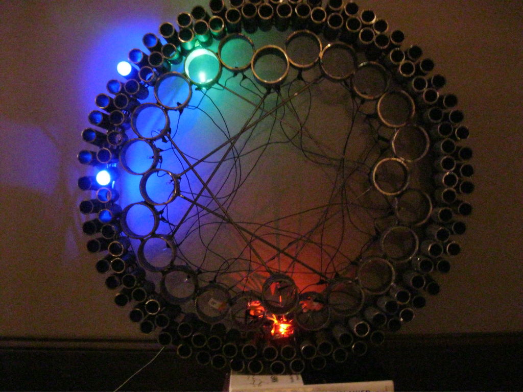
A 24-hour clock with hour, minute, and second indicators. Here’s the catch, despite being a digital media (LED’s) it is still displaying using an analog method (circles!). I finished making this clock months ago but did not bring it with me to school so I wasn’t able to take pictures and all until now. I have been very excited to get this up since I think it is sooooo cool 🙂
It functions as a very pretty piece of functional art. However, it is missing a home since I do not have space where I live for it 🙁 so it is staying con mis padres at the moment.
It is approximately 30″ tall and about 30 lbs? (hard to tell since it is awkward to hold). This makes it difficult to mount to wall (I haven’t tried yet). It actually stands on its own surprisingly well by balancing between two of the seconds rods.
Anyways! enjoy this fantastic piece of art and technology!
Here is video. You can see some ghosting and glitching. The ghosting can probably be solved with just using a slightly higher resistor? the glitches are just because some of the wires are loose. I took this video after a few months of this sitting in the cellar and didn’t bother to go through the long debugging process of ensuring all proper connections…
Step 1: Materials
Materials:
- 120 tubes 3″ long (60 sec + 60 min) = 360″ of tubing = 30 feet of 1″ steel tubing (this is the hardest part to get just because you need so much)
- 24 tubes 2″ long (24 hours) = 48″ = 4 ft 3″ diameter tubing (I used a broken table support for this)
- 100-200 ft of as thin of wire as you can find (magnet wire is a good option). Also, try to get black wire to blend in better.
- 144 LEDs
- 60 for the seconds (choose color A)
- 60 for the minutes (choose color B)
- 24 for the hours (choose color C)
- 24 resistors (100 ohms or close)
- Arduino MEGA (you could work to put it onto regular Arduino but we need 24 I/O pins in this build)
- DS 1307 (found here)
Step 2: Metalwork
The metalwork, although tedious, is fairly simply (assuming you already know how to weld). I am not going to get into all the how-to-weld topics (there are plenty of other ibles and opportunities to learn this elsewhere)…
Here are the metal-work steps:
Step 1: Cut the tubes.
you need to cut 144 three-inch tubes (1″ diameter). I used a horizontal bandsaw with a block clamped down at the 3″ mark to cut as quickly as possibly. While this step takes the most time, it isn’t that challenging. I would not attempt this without a bandsaw or other power tool as there are a lot of cuts to make…
Step 2: Bend a Circle
To create a guide for when it comes to welding the tubes together, we want to make a circle out of a bent piece of steel rod (1/8″ or 1/4″ thick) (1″ wide). The diameter of this circle is set to be 30″ so we need to first cut a length of 30″ x Pi = 94.25″. Then you need to bend or roll the flat length into the curved circle. This is most easily accomplished in a roller (as I did) or you can take the hard, long, and less precise way of just bending it slowly by hand. It isn’t too tough to bend, but it sure wont be as nicely bent as with a roller.
Step 3: Welding
I prefer MIG welding always because it is fast and easy. You can choose whatever welding method / technique you like though. Basically we are just going to make a ton of spot welds. Nothing heavy duty is needed (although you can heavily weld a couple if you want to hang it by them).
With that said, remember your safety!
I found it easiest to start with the minute’s tubes. I welded all 60 tubes to the inside of the guide circle bar. Then you can choose to either do the seconds or the hours. I did seconds next, and lastly the hour tubes. For aesthetics, I spot welded (although I think I used an oxy-acetylene torch) a few small rods to the inside. They are completely not needed. The original idea was to mount the Arduino to the center but I realized this would look ugly so I stuffed it at the bottom.
(it wouldn’t be a bad idea to clean the metal off and de-burr it)
Step 3: Circuit
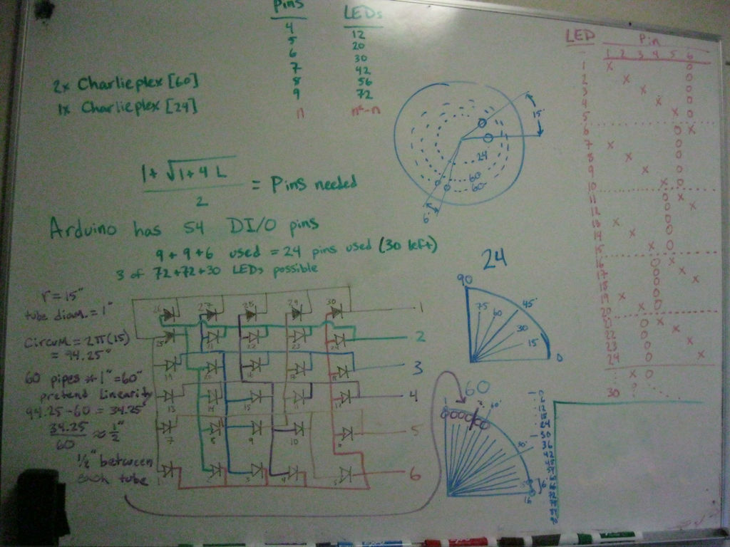
The circuit is based off of charlieplexing. The circuit is best shown in the pictures… which are basically my drawings on a white-board. Each set of time (hours, minutes, seconds) have their own set of pins (no crossover). 6 pins for the hours, 9 for the minutes, and 9 for the seconds. 24 total.
The third picture basically is just me calculating how much space (as in the angle) each 1″ tube takes up and thus what radius circle do I need to hold all the tubes. I also accounted for a little bit of spacing as well. This is how I came up with the 30″ diameter.
The hour circuit is shown in the second picture. As you can see, the LEDs marked 1-24 are in use and the additional 6 LEDs (25-30) are not in use (there isn’t physically anything in their position). The 6 pins shown on the right of picture 2 are the 6 pins needed from the Arduino. These 6 pins control all 24 LEDs for the hour hand.
The chart at the top (in green) on the first picture shows the number of pins needed to control X LEDs using simple charlieplexing. As you can see, n pins can control (n2 – n) LEDs. So to control 24 LEDs we need 6 pins (as claimed earlier) and to control 60 LEDs we need 9 pins.
ignore some of the unnecessary info in green… and ignore the purple and blue… basically, we need 24 pins from the Arduino (or whatever). This means we can’t use an UNO or Due, rather, we need to use the larger Arduino MEGA which comes with 54 pins. It is a shame to waste all those extra pins, but so be it. You could also use an atmega or anything else, the code is fairly simple.
You will also need a DS1307 Real-time clock (as shown at adafruit) if you want the clock to remember the time after turning it off each time. Otherwise you have to manually set the time every time you start it running. This would mean going into the code each time.
The same circuit can be extended from to 6-pin version to the 9-pin version. The hard part comes with the physical wiring… I would recommend starting with the hour’s wiring to get the rhythm before continuing to the more complicated rings.
Step 4: Wiring I
This is the step most prone to errors just because it gets to be a lot of loose wires. Although there is a very clear pattern once you see it. The pattern becomes even more obvious with the 9-pin circles than with the 6-pin hour wiring. However, the 6 pin is more spaced out and is a better place to start to get the hang of the patterns.
I can point you in the right direction and I am glad to offer any advice and answer any questions posted in the comments. However, I firmly believe the best way to do this (resulting in the least errors) is to just try wiring it and that way see the patterns that dictate where each wire goes. This will end up being a lot more helpful than an instruction manual.
The pictures below may come in handy though, at least when starting out. The pictures on this page correspond to how to create each bank of LEDs for the minutes and seconds hands. I started with each LED by bending the shorter lead (-) into a sort of bracket and then ran a slightly curved piece of stiff metal (conductive) wire to connect all of these electrodes. The + leads (longer leads) of the LED were left pointing straight up (down in the picture).