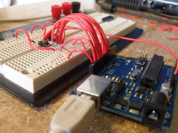
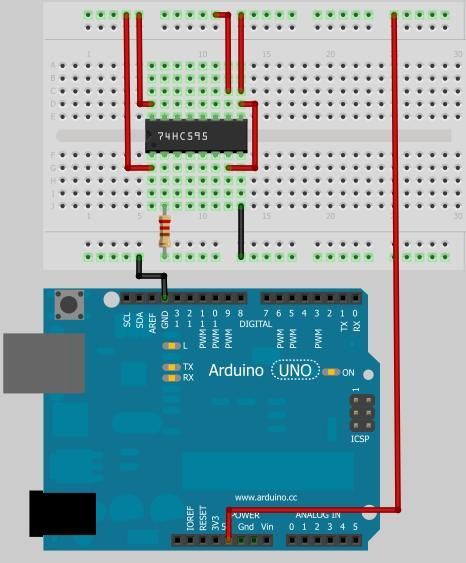
Have you ever needed to count something? Sure, we all need to count change, count blessings, and occasionally count cards, but that’s not really the kind of counting I’m talking about. In this Instructable, I will elucidate how Counting ICs operate, and show how to connect one to a microcontroller so you can see exactly how it works in a controlled way.
Step 1: Why Use Counting ICs?
Yes, yes, why not just use the microcontroller? Arduinos are pretty good at counting things. But what if you want a cheap hardware solution that operates with events as fast as 30MHz? That’s what counting chips are for.
My work in the atom optics lab at my university has taken me through some real twists and turns. I’ve learned more in my two years as an intern there than I have in most of college, and it’s way more rewarding than turning in homework. If you ever have the chance to work in a university laboratory, take it, no matter what. You’ll never regret it. One of the things I’ve had to learn pretty thoroughly is electronics, since one of my duties is troubleshooting electronics and occasionally building additions and hacks to them. My most recent project brought me face to face with digital counting ICs.
The project involved using a Michelson Interferometer to compare the relative wavelengths of two lasers by counting the number of fringes of each beam when a retro-reflector cart was translated across the beam paths, thus changing the path lengths of both beams by identical amounts. Light has such a short wavelength that moving the cart even as slowly as a few centimeters per second produces fringe patterns at around 150kHz. The interferometer operation simplifies down to the relation:
λ2=λ1(N2/N1)
where λ is the wavelength of a laser, and N is the number of fringes produced by translating the cart a certain distance. So if we know one laser pretty well, we can find the wavelength of the second laser by counting their fringes. For light being measured by translating the cart over 1 meter, N is going to be around 40 million. Try counting that by hand. No, we need high speed event counting methods.
Another use would be in something like a Geiger counter. If you need to know how much radiation you’ve been exposed to, you can hook up a traditional Geiger counter to a counter IC and count the number of radiation events, then use the appropriate math to convert the radiation count to rads.
Step 2: Basics of Counter ICs
The basis for digital electronics is that we only care if a signal is HIGH or LOW. Analog is concerned with everything in between, but digital only concerns itself with those two states. Typically, digital electronics use +5V for HIGH and 0V for LOW.
Counter ICs are a complex configuration of NOR gates. NOR gates are a special combination of (at least) four MOSFETS. NOR gates have two inputs and one output. The inputs and output can be either HIGH or LOW. The output state depends on the input states in the following way:
Source: Wikipedia
| INPUT | OUTPUT | |
|---|---|---|
| A | B | A NOR B |
| 0 | 0 | 1 |
| 0 | 1 | 0 |
| 1 | 0 | 0 |
| 1 | 1 | 0 |
So the output is only HIGH when both inputs are LOW. This is the most basic part of a counter. Each of these NOR gates are paired in a configuration called a “flip-flop”. Flip-flops have two inputs (S and R) and two outputs (Q and Q*), and have only two stable states:
| SR latch operation | ||||
|---|---|---|---|---|
| S | R | Action | ||
| 0 | 0 | No Change | ||
| 0 | 1 | Q = 0 | ||
| 1 | 0 | Q = 1 | ||
| 1 | 1 | Restricted combination | ||
The two output states can be chosen between by setting either S or R HIGH. When both inputs are LOW, the flip-flop stores its output state according to whatever input it last received. If we string one of the outputs of one flip-flop to the input of the next flip flop, along with some other necessary connections, then each flip-flop down the line depends on the previous states of the flip-flops before it. The previous states depend on the number of triggering events that the system has received. The first output changes state with each external triggering event, called a clock pulse. The second flip-flop changes state every two clock pulses. The third flip-flop changes state every four clock pulses, and so on, with the number of clock pulses required to change state doubling for each subsequent flip-flop.
But what happened to the other flip-flop output? There were two for each one. In fact, each extra output represents one bit of information. If we were to test the voltages of these outputs after sending the counter a certain number of clock pulses, we would see:
| Clock Pulse | Output |
|---|---|
| 0 | LLL |
| 1 | LLH |
| 2 | LHL |
| 3 | LHH |
| 4 | HLL |
| 5 | HLH |
| 6 | HHL |
| 7 | HHH |
Which is binary code! With this configuration, we can only count 8 different states, but by adding another flip-flop, we could count to 16. With two more, we could count to 32, and so on! The table shows a three bit counter. If we had an 8 bit counter, it could count up to 256, and would be able to store one byte of information! If we string two 8 bit counters together, we can count up to 256*256=65536! Depending on how many events you need to count, you can just string a bunch of counters together and reach the appropriate counting limit. Counters in this configuration are called “ripple counters”, since the state of the previous flip-flop ripples along to the next flip-flop. There are many other types of digital counters, but this is the easiest to understand.
For more detail: Learn Counter ICs Using an Arduino


