Interfacing hex keypad to arduino.
This article is about how to interface a hex keypad to arduino. Hex keypad is a very important component in embedded systems and the typical applications are code locks, calculators, automation systems or simply any thing that requires a character or numeric input. This project will display the pressed key in the serial monitor window of the arduino IDE. The same project can be modified to display the pressed key on 7-segment LED display or an LCD display. Before going into the details, have a look at the hex keypad.
Hex keypad.
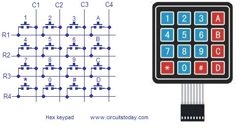
Hex key pad is simply an arrangement 0f 16 push button switches in a 4X4 matrix form. Typically a hex keypad will have keys for number 0, 1, 2, 3, 4, 5, 6, 7, 8, 9 and letters A, B, C, D, *, #. The hex keypad will have 8 connection wires namely R1, R2, R3, R4 and C1, C2, C3, C4 representing the rows and columns respectively. The schematic diagram and photo of a typical hex keypad is shown in the figure below.
The program identifies the pressed key by a method called column scanning. In this method a particular row is kept low and other rows are held high. The the logic status of each column line is scanned. If a particular column is found low, then that means the key that comes in between that column and row is short(pressed). Then the program registers that key being pressed. Then the same procedure is applied for the subsequent rows and the entire process is repeated. For example if row 1 is kept low and column 1 is found low during scanning, then that means key”1″ is pressed. Full circuit diagram of interfacing hex keypad is shown below.
Circuit diagram.
Rows R1, R2, R3 and R4 are interfaced to digital pins 6, 7, 8 and 9 pins of the arduino respectively. Columns C1, C2, C3 and C4 are interfaced to the digital pins 10, 11, 12, 13 of the arduino. The arduino is connected to PC through the USB port. The circuit is powered from the USB itself and no external power supply is needed. The full program for interfacing hex keypad to arduino is given below.
Program.
int r1=6; int r2=7; int r3=8; int r4=9; int c1=10; int c2=11; int c3=12; int c4=13; int colm1; int colm2; int colm3; int colm4; void setup() {
For more detail: Interfacing hex keypad to arduino