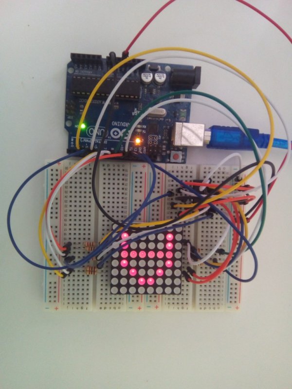
LED matrix displays can be used to display almost anything. Most modern LED sign boards uses various types of matrix boards with controllers. In this tutorial we are going to interface a single color 8×8 LED matrix with Arduino and display a few characters in it.
8×8 matrix consists of 64 dots or pixels. There is a LED for each pixel and these LEDs are connected to total of 16 pins. You can identify the pin out and circuit diagram of it using the following figure.
As you can see all anodes of same row is connected to one pin and all cathodes of same column are connected to another pin.We have 8 row pins and 8 column pins. If a positive voltage is applied to R1 pin and negative to C1, we can see that the first pixel turns on. If we apply negative to C2 then the second pixel turns on. Like this we can turn each pixel by hanging the supply pins. However we have 64 supply combinations, and doing it manually is practically impossible. This is why Arduino is interfaced with the 8×8 matrix.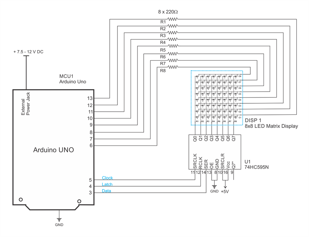
Arduino Code
int latchPin = 4; // pis connected to shift registors
int clockPin = 5;
int dataPin = 3;
int pins [8] = {6, 7, 8, 9, 10, 11, 12, 13}; // common cathode pins
byte A[8] = {   B00000000, // Letters are defined
                B00011000,// you can create your own
                B00100100,
                B01000010,
                B01111110,
                B01000010,
                B01000010,
                B00000000
            };

byte B[8] = {     B00000000,
                  B11111100,
                  B10000010,
                  B10000010,
                  B11111100,
                  B10000010,
                  B10000010,
                  B11111110
            };

byte blank[8] = { B00000000,
                  B00000000,
                  B00000000,
                  B00000000,
                  B00000000,
                  B00000000,
                  B00000000,
                  B00000000
                };
byte R[8] = {  B00000000,
               B01111000,
               B01000100,
               B01000100,
               B01111000,
               B01010000,
               B01001000,
               B01000100
            };


void setup() {
  Serial.begin(9600); // Serial begin
  pinMode(latchPin, OUTPUT); // Pin configuration
  pinMode(clockPin, OUTPUT);
  pinMode(dataPin, OUTPUT);
  for (int i = 0; i < 8; i++) { // for loop is used to configure common cathodes
    pinMode(pins[i], OUTPUT);
    digitalWrite(pins[i], HIGH);
  }

}
void loop() {


  for (int k = 0; k < 1000; k++) { // showing each letter for 1 second
    display_char(A);

  }

  for (int k = 0; k < 1000; k++) {
    display_char(B);

  }
  for (int k = 0; k < 1000; k++) {
    display_char(R);

  }
Rear more: Interfacing 8×8 LED Matrix with Arduino