What is it?
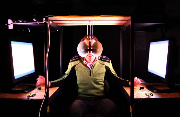
This is an ongoing project that i’ve been working on to see the potential of interactive stereoscopic installations in examining the perceptual process. I use a setup that i’ve called a Diplopiascope to investigate this. The Diplopiascope has gone through a few changes but basically it is a stereoscopic viewer that allows the viewer to control the images they are being shown through an analog device.
How does it work?
Stereopsis is the perception of depth through an object being seen with both eyes. Due to the horizontal separation of the eyes, two slightly different views of the same scene are shown to each retina. This information, along with several other cues, is used by the brain to calculate depth.
This effect is simulated in the Diplopiascope by presenting stereoscopic films or images to the left and right eyes via projectors or monitors. The viewer is seated and views the images simultaneously through a mirrored viewing device.
I was interested to see what happens when we present different views to each eye at the same time. This is called binocular rivalry. What happens if we show the same scene at different times? What about greatly different viewpoints of the same object? What if the viewer is put in control of what they see through some physical controls?
This tutorial is more a guide to making the viewing apparatus for experimentation than a physiological explanation of stereopsis itself, and it doesn’t go into much detail about how to make stereoscopic films as there is already lots of great information about this online.
Here are two videos of the Diplopiascope being used. The designs are slightly different but the idea is the same.
The videos of the drummer used in the installation above were shot with two cameras from a fixed position. The videos were then looped and projected independently. The videos are viewed through a mirrored viewing device, the left eye being shown the footage from the left camera, the right eye the footage from the right. (In actual fact, the videos are inverted horizontally due to being seen through mirrors. To counter this, the videos were inverted horizontally in the projector settings).
Due to the videos being ever so slightly different lengths (about 100 milliseconds), when looped they become increasingly out of synch. Because of this, while the stationary objects in the video (the drum set, wooden frame, cones, walls, etc.) are seen in crisp stereoscopic 3D, the moving objects (the drummer, people, etc.) will be seen in double. This produces a strange effect as the brain switches uncontrollably between which information it perceives, jumping randomly from the left eye to the right dominating perception. What it looks like is difficult to explain, but the moving objects take on a very strange phantom-like presence in the realness of their solid stereoscopic surroundings. While the majority of the field of view remains fixed in pleasant 3D, the figure of the drummer seems to jump in and out of time frames and consciousness itself.
The speed and direction of the videos are controlled by the viewer through an analog device connected to the PCs via arduinos.
There are two speakers, one from each PC, and the audio matches the videos and is also controlled by the dials.
The video above shows a slightly different version of the installation. The principle behind the viewing method remains the same, but one difference is the actual videos being show. In the first example, the videos were shot stereoscopically from a fixed position. In this case, the videos were shot using a mobile camera rig (detailed later). The rig is designed so that it can break apart and come together again seamlessly. By filming along two long pathways of shrine gates, I wanted to see what happened if the left camera (left eye) went down one path and the right camera (right eye) down the other. The left and the right pathways in the video are very similar, but not identical. Would our brains be able to compensate for the little differences in the scenes we see? Would we perceive a unified view of one solid pathway, or would it just give us a headache?
Again the speed and direction of the videos are controlled by dials so the viewer can adjust the images they are being shown. By doing this they are able to play around with uniting and rupturing their visual perception.
Step 1: Project parts
[box color=”#985D00″ bg=”#FFF8CB” font=”verdana” fontsize=”14 ” radius=”20 ” border=”#985D12″ float=”right” head=”Major Components in Project” headbg=”#FFEB70″ headcolor=”#985D00″]
Hardware
To make the films: Identical camcorders/ videocameras (x 2). I used JVC Everio camcorders that I bought in Japan from an online discount shop for around 14000 Yen ($140) each.
Analogue inputs: I used 2 potentiometers for these projects but other sensors could be more interesting. I attached dials to the tops.
Arduino Uno (x 2)
Displays: Identical monitors or projectors (x 2). These can be very expensive so it’s always best to borrow them.
Laptop (x 2). It is possible to use only one macbook with a Matrox DualHead2Go to send output to 2 displays but it starts to get a bit messy with two arduinos running on one macbook or two analog signals going to one arduino. Max/MSP starts to get a bit heavy too.
Viewing device: 2 mirrors set at 90 degrees. I used cheap circular ones from the 100 Yen shop.
[/box]
Software
Arduino (free)
Max/MSP (free 30 day trial available from the website)
SleepLess (This is for display purposes only. It allows you to close the macbook lid but continue to run the programs). I was using two different macbooks and had to use different SleepLess versions on each. I used version 2.8.3 on the Lion 10.7.5 and version 2.6.2 on the Leopard 10.5.8. There are various disclaimers on the SleepLess download about the risk of overheating, so it’s probably best to have a look at those. I ran the PCs for 8 hour stretches over a week or so without a problem.
Step 2: Making the stereoscopic films
There are a number of different ways to make stereoscopic films, but because my interest is in showing slightly different images to each eye, rather than just a finished stereoscopic film, there is no need to use an expensive stereoscopic camera. I found these cheap JVC camcorders did the job just fine.
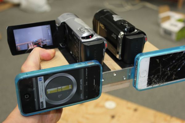
I built a simple frame out of 1cm MDF board with holes drilled through the bottoms to attach the cameras with bolts. They were fixed with the centre of the lenses 7cm apart to reproduce the distance of the eyes (the binocular parallax).
This is the basic frame and can be used for simple projects. If you want to experiment further with divergence and convergence of the images then you may want to be able to separate the cameras at one point, while continuing to record, and then bring them back together again seamlessly. In this way I hoped to further simulate binocular rivalry. To do this I cut the rig in half down the middle and built in some steps that can be pulled apart and brought back together again with the aid of metal guides made out of brackets. I attached iphones to the backs of each half of the rig. By running a spirit level app on the iphone it is possible to keep both cameras pretty much level while they are split and filming independently.
As mentioned in the intro, I made a few different pairs of stereo videos to see what was interesting. However you decide to shoot the videos (from a fixed position, moving around holding the rig, splitting the rig, etc), once they are recorded you should transfer the files to the PCs: the data from the left camera goes to the PC that will show the information to the left eye, the data from the right camera goes to the PC that will show the information to the right eye.
If you want to use some videos I made using the split-rig idea as a test, they are available to download here. There are two videos in the folder. “L3 show.mp4” is the data from the left camera, “R3 show.mp4” is from the right.
Remember that you need to take into account horizontal inversion because you are seeing the images through mirrors. To counter this, you must either put the data from the left camera onto the right PC and the data from the right camera onto the left PC (and view the videos in an inverted state), or invert the videos either on the PCs, monitors or projectors.
There are many great designs for stereoscopic camera rigs that can be found online. This was the cheapest, simplest, and most practical that I could think of. I’m sure there are far better designs for mobile filming so if anyone has any advice i’d love to get your feedback.
Step 3: Making the viewer
The viewer is a very simple device made of two mirrors set at an angle of 90 degrees to each other. When looked at straight-on, you are able to look in two totally different directions without discomfort.
There are many ways to make the device. I wanted something simple that wouldn’t distract the viewer from the videos. I used two 90 degree brackets welded together to make the main part of the frame. I then attached the mirrors using a combination of industrial strength double sided tape and hot glue. I used threaded rods and bolts to secure the device either below or above. I used 4 threaded bolts to prevent any wobbling from back to front or side to side.
Much simpler viewers can be made using two rectangular mirrors placed together at 90 degrees. In fact, there are many ways of viewing stereoscopic images using lenses, anaglyph/ polarised glasses, or HMDs. I like using mirrors as there is no “black box”; the mechanism is transparent and doesn’t distract from experience itself.
Step 4: Making the analog input devices
Now we are going to make the dials to control the video speed and directional playback. I made two controls, one for each hand, to control the information going to each eye.
I used two cheap potentiometers (pots) from the electronics shop and attached dials to the tops. The pots have 3 pins. Attach and solder lengths of jump wire to each pin. The left pin (when the pins are pointed away from you) goes to the arduino 5V, and the right pin goes to arduino ground (GND). The central pin is the output and this goes to the analog input pin of your choice on the arduino. For the Max/MSP patch that comes later I used analog pin 19 (A5). If you use a different pin on the arduino then you will need to go into the patch and change the settings. This is a good reference for connecting analog reads.
The photographs above are best not used as references when working out which pot pin goes to which arduino pin because there are several different colours of wire soldered together (I ran out of wire).
For display purposes, you can either thread the wires through the table (or whatever you are using) before connecting them and attach the arduinos underneath with screws, keeping them hidden from view, or simply leave them out on top. I fixed the pots by cutting out circular holes in the wood at positions comfortable to reach with both hands while seated. Hot glue is good to hold them in place.
This is the part of the project that interests me the most: where physical interaction on behalf of the viewer generates a change in perception. This is the first time i’ve used arduino to convert analog input to digital output, and the analog device is very crude, but I think there are lots of interesting possibilities.
If anyone has any good ideas for others sensors that might be interesting i’d be really grateful for feedback. I thought about maybe using an accelerometer to make a device that requires movements more appropriate to the content of the video. In the case of the drummer, for example, could accelerometers attached to drum sticks work as the analog input?
Step 5: Setting up the Arduino and making it talk with Max/MSP
After wiring up the arduino with the analogue device, as described in the previous step, it’s time to move onto the software.
We are going to use Max/MSP to receive the analog signal and convert it to digital to control the video playback. To do this, we need to upload an arduino code and a Max patch.
Get the software
First, make sure you have downloaded and installed the arduino software and have a version of Max/MSP (you can get a free 30 day trial). I’m using Max6 but 5 works too, below that i’m not sure but I don’t see why not.
There are many different ways to get the arduino and Max talking to each other. I found that the simplest is called “ArduinoMax_InOut_forDummies”. Maxuino seems like a great open source project with a healthy forum community but I couldn’t get it to run smoothly. Any advice here would be much appreciated!
Download the arduino code and Max patch in the “diplopiascope.zip” folder here. (The original file that my patch is based on is available for download at the bottom of the Arduino Playground page).
There are 3 files in the folder:
1. “arduinoMaxinOutforDummies.ino”: this is the arduino code to make it talk to Max.
2. “diplopia.maxpat”: this is the the max patch that we will use to receive the signal from the arduino and control the video playback. It is based on the original ArduinoMax_InOut_forDummies patch.
3. “ArduinoMaxinOutDummyCom01.maxpat”: this is the setup for the max patch and needs to stay in the folder along with the “diplopia.maxpat” file for the patch to work.
The Max patch that I developed uses a max external to give smoother values from the analog input. This needs to be downloaded from here and then installed as described in the “info.txt file” in the folder.
All of the above steps need to be done on both PCs.
Upload the arduino code
Connect the arduinos to the corresponding PCs via USB cables.
Open the “diplopiascope” folder and upload the arduino code “arduinoMaxInOutforDummies.ino” onto each arduino.
The message “done uploading” should be displayed in the arduino window.
For more detail: Interactive Stereoscopic Installations: visual rupture with the Diplopiascope