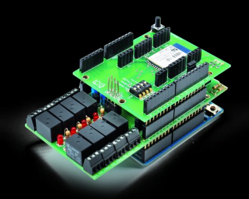
Today we’ll expand Arduino’s digital resources thanks to an I2C bus equipped shield and we’ll allow the management of the board via a bluetooth connection RN-42 through an Android systems.
All Arduino boards feature a number of digital I/Os. For the simplest projects, such resources are usually more than sufficient, but in those where they you need several control lines, “standard” I/Os can be less than enough, because some pins are shared with internal resources while others are dedicated to external shields.
In these cases, a possible solution is to switch to more powerful Arduinos (for example, the Mega, which has more I/Os than the classic Duemilanove or Uno) or use special expansion shield. In this article, we present one shield that allows you to add I/Os that can be handled very simply via an I²C bus data channel. The shield is basically what we call “I/O expander”. I²C bus management is provided by MCP23017 integrated circuit manufactured by Microchip.
The bus is made of three wires: one is the (common) ground while the other two are SCL (a clock that marks the communication) and SDA (Bi-directional serial data). In the I²C-Bus protocol the beginning of each communication session comes from a Master unit (Slaves can only reply to the Master), which sends 8 bytes commands, one of which contains the address of the Slave which is directed to. Since the address is made by one byte, the I²C-Bus could theoretically support 128 devices but you can only use 112, since 16 addresses are reserved. The identification of the individual slave units is usually done by setting the appropriate combination logic on the lines for which each integrated is provided: these lines are usually three allowing 8 combinations.
In our case, the ability to define the destination of the I²C-Bus commands allows us to connect several I²C I/O Expander board at the same time by stacking them one on top of the other. Each expansion board has 8 relay outputs and as many digital inputs, the I²C address of the MCP23017 chip can be selected from eight possible, so you can mount eight shield, until a total of 64 relay outputs and 64 digital inputs .
On top of this smart system we decided to add Bluetooth control, in order to manage it from a smartphone. To be super cool, we added our Bluetooth RN-42 shield, and we developed a special app for Android that allows you to view the status of all digital resources and send commands to activate outputs.
Being the overall system modular (you can add and remove Expander shields at will) it lends itself to different end-user applications. Both the Arduino firmware and the App will adapt: the firmware is indeed able to detect how many (and which) Expander shields are present while the App receives such information from Arduino and consequently adapt its own graphical user interface.
The App has a special configuration page that makes possible to set text labels to be used for the description of the I / O resources, thus adapting to your particular hardware configuration. Finally, there is a bluetooth setup page where you can set your name and pin code to be matched to the RN-42 shield.
The circuit diagram of a single expansion shield has been developed around the U1 component, namely Microchip’s MCP23017. Find more info in the previous post.
Outputs end on U2, the ULN2803, specially designed to drive inductive loads such as relay coils (in fact, has several transistor stages with protection diodes of the base-collector junction).
Inputs (B port) are connected to appropriate circuit sections which carry the digital inputs. Each input has a protection diode, a pull-up resistor, and an LED that indicates the status. When the input is logically low (to ground) the corresponding LED is lit, and the I/O Expander shows that the input is “0”, whereas, when the input is high, the LED is off and the I/O Expander indicate that the input is “1”.
MCP23017 management happens though the I²C Bus protocol and by reading and writing specific registers. The SDA and SCL lines are available on pins 13 and 12, which, as you see in the wiring diagram, are taken to the corresponding pins of the Arduino board. As the MCP23017 has the ability to generate an interrupt when at least one pin programmed as input changes state, we used this function to handle inputs from the Arduino in interrupt mode instead of polling (thus being faster and without burdening the I²C bus). The interrupt allows you to initiate a connection, with the the Arduino operating as the Master unit. Clearly, as we’ll see later, the software must be specially crafted to take advantage of this feature.
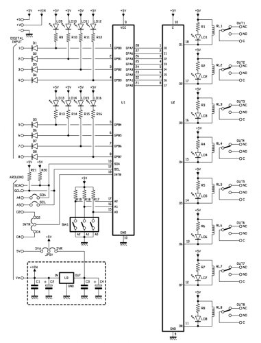
Thanks to a jumper we left the possibility of bringing the MCP23017 interrupt pin (INTB, 19) as input on 2 different Arduino pins (D2 or D4) to fit as much as possible to the actual use.
MCP23017’s I2C address is selected via SW1 dip-switch: 3 dips are present therefore it is possible to connect up to 8 different shield without interfering with each of them.
Finally, there is a power supply section composed by the regulator U3 (integrated L78L05) which transforms the input voltage Vin to 5 volts needed to operate the entire circuit. Through the JP5V bridge you can choose to bypass the regulator but directly use the 5V supplied by the Arduino board.
For more detail: An I²C Bus powered Arduino IO Expander Board controlled via Bluetooth and Android