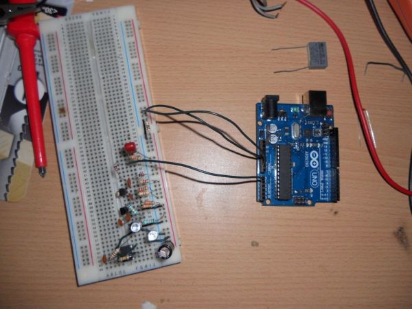
Here is my instructable on how to construct a pretty simple (for some!) short range infrared rangefinder/range sensor. Infrared rangefinders are very useful in a number of projects. The majority of these come from obstacle detection (in robots) or generally detecting distances! The one shown here is only a simple rangefinder and will only really be able to measure about 6 or 7cm infront of the range finder. Luckily, most objects reflect infrared well enough to produce a reading (including a hand, paper and tin foil). I will be showing you how to use the infrared range finder with an Arduino and ways of linearizing the result.
Step 1: Theory
The theory behind an infrared rangefinder is that pulsed infrared is emitted from an IR led and then reflected back off an object into an IR receiver. As light adheres to the inverse square law which states that as distance from a source is increased, the intensity decreases by the square (Source: http://hyperphysics.phy-astr.gsu.edu/hbase/vision/isql.html). Essentially, the light is emitted by the infrared LED, which then bounces off the object. In the first instance, the LED is the emitter and the reflective object is the observer. Once the light hits the object, it then bounces off and is reflected back to the IR receiver. The object is then acting as the source of light so the inverse square law takes effect twice. This has the problem that the maximum range of the rangefinder is quite short and to increase the range, higher power LED’s would be required.
Another problem that takes affect with light based rangefinders is how it can be affected by ambient light. I fix this in my rangefinder by modulating the emitting LED. Without this modulation, a simple light bulb connected to the mains can affect the result by superimposing 50Hz onto the actual signal.
My rangefinder works through having a modulated IR source at an ultrasonic frequency, being detected by a IR receiver (IR photodiode) which is then fed into a high pass filter, amplified and peak detected.
Step 2: Step 1: Making the IR transmitter
The first step is to create the IR transmitter. As a simple transmitter, I’m using a 555 timer as an inverting Schmitt trigger to create an astable oscillator. Using the 555 timer in this fashion reduces the amount of components required to one resistor and one capacitor. Using a 555 timer isn’t particularly stable as the tolerance of both capacitor and resistor affects the frequency, along with temperature changes. Since the infrared receiver is then only high pass filtered, as long as the filter cut off frequency is below the operating frequency of the transmitter, the filtering properties will work. As can be seen in the schematic diagram, the red section is the transmitter.
With the resistor and capacitor values chosen, the operating frequency will be ultrasonic at a frequency around 46kHz. As stated, this will be both temperature and supply voltage dependent.
It may seem to some that the LED is operating at a current higher than normally specified but since the duty cycle isn’t 100% and is being pulsed, the average current will be below the specified 20mA. When building this section, a 100R Resistor was used.
A 555 timer is set up as an inverting schmitt trigger by connecting the trigger to the threshold and connecting the reset to the positive supply. A timing resistor is then placed from the output to the trigger (or threshold, since they’re both connected) and a capacitor is placed from the trigger to ground.
Since the 555 timer is more effective at sinking current then sourcing current (take a look at the schematic diagram, the output stage consists of a darlington pair as the current source and a single transistor as the current sink), the LED is connected from the positive source through a resistor to pin 3 (or the output) of the 555 timer.
Step 3: Step 2: Making the IR receiver
In making the IR receiver, I combined the phototransistor with a transistor to create a quite high gain buffered IR receiver. This works through having the phototransistor in the feedback loop of a common emitter transistor amplifier. Since only a few electrons flows per photon in a phototransistor, gain is required. When creating this section, you have to ensure that the phototransistor is correctly biased.
The phototransistor I used was the L-53P3C bought off eBay for a very cheap price. Any suitable photodiode or phototransistor can be used, just ensure that the spectral response matches that of your IR transmitters. Using a IR filtered photodiode/phototransistor will be even better.
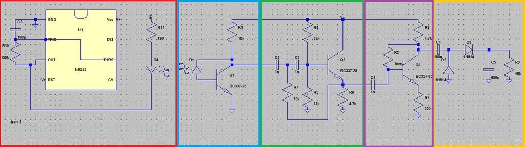
The data sheet states that the maximum on current is 1mA meaning that the worst case scenario will be with current flowing directly through the 18k resistor, into the photodiode and directly from the transistors base to ground, equivalent to a current of 4.3/18000 (4.3 coming from the 5v power supply, minus the 0.7v base to emitter drop, this is as if the transistor was not conducting current through the collector). This gives us a maximum worst case current of 0.238mA, well within the specified current.
The IR receiver is the blue section of the schematic diagram. On the schematic, I have showed how to connect a photodiode. If you’re using a photo transistor, just connect the emitter of the phototransistor to the base of the normal transistor and the collector of the phototransistor to the collector of the normal transistor. This creates a kind of darlington pair.
The phototransistor I used was bought from:
http://www.ebay.co.uk/itm/Infra-Red-Remote-Phototransistor-Receiver-L-53P3C-/200648166002?pt=UK_BOI_Electrical_Components_Supplies_ET&hash=item2eb7900a72
[box color=”#985D00″ bg=”#FFF8CB” font=”verdana” fontsize=”14 ” radius=”20 ” border=”#985D12″ float=”right” head=”Major Components in Project” headbg=”#FFEB70″ headcolor=”#985D00″]IR Transmitter
IR Receiver
High pass filter
Common emitter Amplifier
Peak detector[/box]
For more detail: Homemade Infrared Rangefinder (Similar to Sharp GP2D120) using Arduino