Introduction
(Latest updates 29/3/2015) If you’ve read my early blogs you’ll know I do a lot of work with a pal of mine, Aidan Ruff. We had an R&D company for years and one of our products was a home control system which was plastered all over the UK tech press at the time and loads of people loved it but it involved spouse-unfriendly WIRES – bad mistake. Well, this DOESN’T.
The two of us have been working on home control for several years and regular readers will know that in the past few months, the ESP8266 boards have turned everything around. I’ve scrapped various radio designs and gone “hell for leather” into using these boards, this original plan was with an Arduino Mega as a “master controller”. That too went out of the window when the Raspberry Pi 2 came out, dirt cheap but with more than enough power to control a house. Armed with a WIFI USB dongle, the basics of a completely wireless home control setup are now in place. Personally it could not be better timed as we’re moving house shortly and so this is an ideal opportunity to do the job properly before inflicting this on other people.
The ESP8266 boards have recently taken the IOT world by storm as providing a REALLY low-cost entry solution into the world of IOT (Internet of Things) making it possible to create in the simplest sense an Internet-controlled LED for just £2 or so (it could just as easily be a 2KW heater of course).
There are a number of variations on the ESP8266 boards, the most popular being the ESP-01 – a simple board with power, a couple of IO lines and serial in and out. The thing is – they all use the same chip and that particular board (the ESP-01) is very limited – and for no good reason – the ESP-12 for example has several IO lines and costs the same amount! It’s only downside is 2mm spacing pins but for VERY little you can buy adaptors to 0.1” – or of course use a board that will take the ESP-12.
The Board
For the reasons stated I’ll discuss here the ESP-12 as that is our new favourite sub-module – but the same code applies to all other variations where pins allow. We now have working software – and a circuit board to go with it. For reasons best known to my pal Aidan we’ve called this the Hackitt and Bodgitt board. So from here on I’ll refer to the board as the H&B board. The second iteration of these boards should reach us in April.
Note that a particularly nice feature of this board is that it can be programmed from a standard FTDI and importantly – without messing with links thanks to an on-board Tiny-85 which handles the reset operation. Simply program the board as you would an Arduino. Absolute doddle!
So in terms of “Features”:
- Mains-powered WIFI controller board
- FTDI-compatibility with auto-reset function
- Accommodation for solid state or mechanical relay output
- Temperature sensing using either popular type of sensor
- All signals brought out to edge connector
- Fits in an inexpensive box available on Ebay
- Uses inexpensive power available on Ebay
- Debounced input also acts as manual over-ride for main output
- 2 spare outputs
- RGB WS2812b output able to handle 300 or more serial LEDs
- Thermostatic control commands including 2 sets of on-off times and frost fallback
- More on the way
- Flashing status indication that the unit is functioning and has the correct time which it maintains internally in between updates
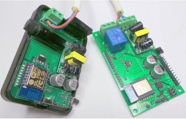
What you see below – are two boards – the one above and a small mains control board designed to fit into a standard Maplin plug-in-the-wall controller box – complete with fuse (how many times do you see THAT!!).
The Controller
The ESP-12-based controller has a number of inputs and outputs which can be controlled equally well by MQTT commands or serial data.
To talk to the unit wirelessly via the popular MQTT message protocol, a message can be sent to the topic “toesp” to send to all units in the network or to a specific unit by prefixing the topic with the unit id. For example “999/toesp”. The only difference between these two topics is that the former will never elicit a response from any unit, the latter MAY, depending on the context, elicit a response.
Each command starts with an open brace and ends with a closing brace. In the case of MQTT, this information is stored in the message body. For serial, there is no “topic”.
An example of a simple command might be to turn output 1 ON (output 1 goes to pin GPIO-0).
{out1:1}
It is possible to send multiple commands at once by separating them with semicolons. i.e.
{out1:1;out2:0}
So to use serial – this is all that is required – for MQTT – the topic should be as referred to earlier and the body of the message should be in the format shown just above.
For more on MQTT go here. http://mqtt.org/
The following document details all the commands the units will respond to – the actions which will occur and any outgoing serial message or MQTT message created as a result of the command.
The Pins
Here we see a drawing of the ESP-12 board, please note there is a question mark over the positioning of GPIO-4 and GPIO-5 – on my test units these were reversed.
You are looking at the FRONT of the unit with the metal cover visible.
Note: In the current software, GPIO12 is used as the Serial RGB controller, tested to and equipped for up to 300 LEDs.
Note2: Contrary to the diagram, in prototyping I’m using a 1k to pull GPIO15 down as it’s still a grey area (some say the board won’t program unless GPIO15 is held down) – it does NOT have to be fully grounded and as you’ll see in fact I’ve added PWM output on it (March 26, 2015).
For More Detail :Home Control 2015 using Arduino