Home Automation through Wi-Fi connectivity (Arduino MKR1000) and Windows 10.
Things used in this project
Hardware components |
||||||
 |
|
× | 1 | |||
|
× | 1 | ||||
 |
|
× | 1 | |||
 |
|
× | 1 | |||
 |
|
× | 1 | |||
|
× | 1 | ||||
 |
|
× | 1 | |||
 |
|
× | 1 | |||
|
× | 1 | ||||
Software apps and online services |
||||||
 |
|
|||||
 |
|
|||||
Story
Nowadays, technology makes our lives easier. It evolves with huge steps and makes it easy for us to create great projects with low cost. So, by using technology we can build a really great home automation system. With the use of an Arduino MKR1000 board with it’s Wi-Fi capabilities in combination with Windows 10 we can create a smart home that could also help people with movement difficulties control every device in the house with one click from their Windows 10 device.
What will you Build?
You will build a home automation system with which you can control every electric device in your house, such as a light bulb, the air condition, a fan, the water heater and anything else you want. You will be able to control your devices through a Windows 10 device (computer, tablet, smartphone) by developing a Universal Windows App (UWA).
Let’s Begin
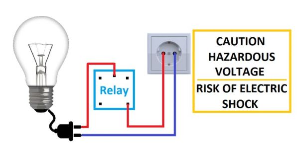
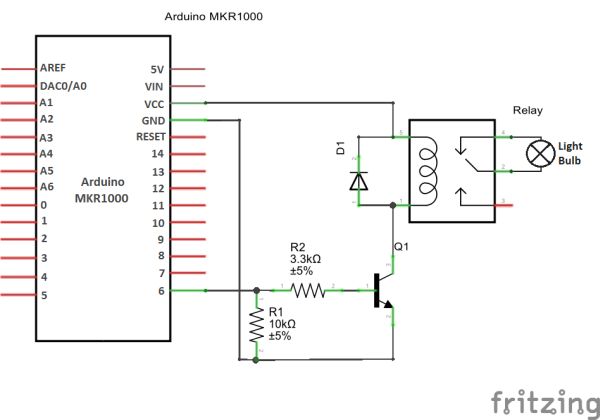
In order to control mains voltage current from a lower voltage device (3.3V) we will use relays. We will need one relay for every device.
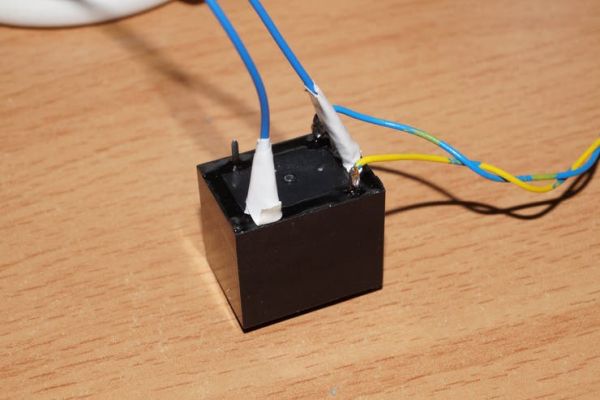
While connecting the relay to your device be sure to UNPLUG the device from the wall socket, else there is high RISK OF ELECTRIC SHOCK. After making the connection use insulating tape to insulate the bare cables.
Using Firmata Library with Arduino
In order to control Arduino remotely (through the UWA) we need to upload StandardFirmataWiFi to the Arduino MKR1000.
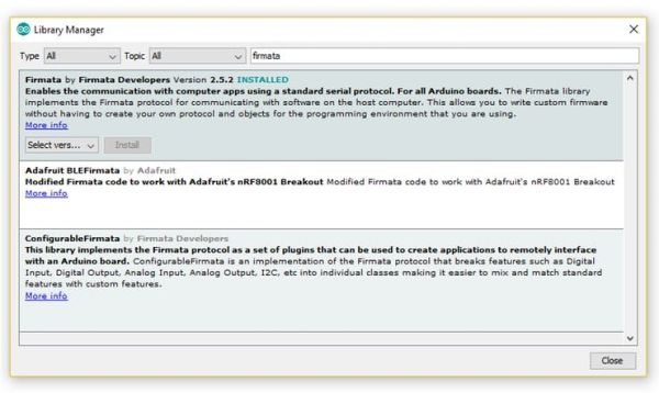
In the Arduino IDE, update the Firmata library to the latest version available from “Library Manager” (Sketch -> Include Library -> Manage Libraries…).
Open: File -> Examples -> Firmata -> StandardFirmataWiFi.
Go to wifiConfig.h tab and comment the line (by adding // in the beginning) #define ARDUINO_WIFI_SHIELD and uncomment the lines (by removing //) define WIFI_101 and #define STATIC_IP_ADDRESS 192,168,1,113. Replace the predefined Static IP Address with one of your choice. Then replace your_network_name with your router’s ssid and your_wpa_passphrase with the password. Note that if your router has WEP security or no security you will need to comment the line #define WIFI_WPA_SECURITY and uncomment #define WIFI_WEP_SECURITY or #define WIFI_NO_SECURITY respectively. For WEP fill in your password in wap_key[] variable instead of wpa_passphrase[].
You are ready to upload the sketch to your Arduino MKR1000.
Developing the Universal Windows App
For this part you will need to download and install Microsoft Visual Studio Community Edition.
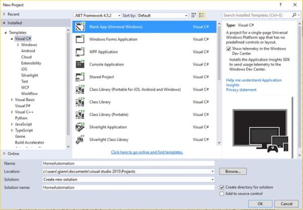
- Open Microsoft Visual Studio and create a new project (File -> New -> Project…). Then from the menu on the left choose Visual C# (It is located under Installed -> Templates) and click Blank App (Universal Windows). Give it a name (e.g. HomeAutomation) and click OK.
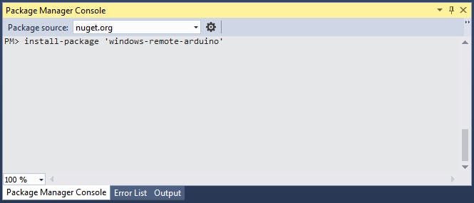
- Go to “Package Manager Console”, write install-package ‘windows-remote-arduino’ and press Enter to add Windows Remote Arduino to your project.
- From the “Solution Explorer” right click Package.appxmanifest and choose View Code. Under the Capabilities tag add Capabilities “internetClientServer” and “privateNetworkClientServer”.
<Capabilities>
    <Capability Name="internetClientServer" />
    <Capability Name="privateNetworkClientServer" />
</Capabilities>
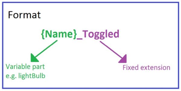
- Open MainPage.xaml in order to create the User Interface. From the Toolbox drag and drop as many ToggleSwitches as the number of the devices you want to control. For each one you need to edit the properties. So under the Properties tab, give the toggle switch a Name (e.g. lightBulb), under “Common” edit the Header (e.g. Light Bulb). Then switch tab by clicking the Event handlers button and fill in the “Toggled” cell with an appropriate method name (e.g. lightBulb_Toggled). For this part you should use a specific format in all your toggle switches in order to have homogeneity.
- Code files: Home Automation
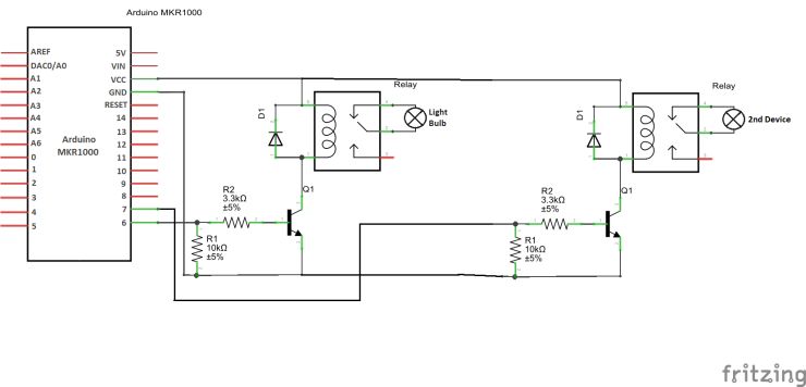
Extending the Project
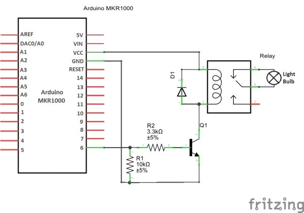
In order to control more devices follow this schematic:

For each device you will need a relay, an NPN transistor, a 10k ohm and a 3.3k ohm resistor as well as a diode.
Schematics
Code