Being able to control everything from your pocket has long been a dream shared by many. Previously we’ve had universal remotes that can both control our TVs and radios, then we had wireless wall sockets. Both great things, but how likely is it that you’re going to be carrying around those remotes with you everywhere you go? These days almost everyone has a smartphone in their pocket, so why not use that?
So that’s what I did.
I can now control electrical sockets and the main lights in my house using my iPhone. It’s all totally wireless and you can set up smart run-times within it (e.g. when you press the shower button it will turn on the boiler, the bathroom lights and the upstairs lights, after 1 minute it’ll turn off any downstairs lights that are still on and then after two minutes it’ll turn off the upstairs lights, and after 20 minutes it will turn off the bathroom lights).
By using basic electrical knowledge, taking apart some readily available items and writing some arduino code you to can make yourself a robot butler (mine’s called Geoffrey).
Let’s get started!
Step 1: What you’ll need
[box color=”#985D00″ bg=”#FFF8CB” font=”verdana” fontsize=”14 ” radius=”20 ” border=”#985D12″ float=”right” head=”Major Components in Project” headbg=”#FFEB70″ headcolor=”#985D00″]
Tools you will need:
• Knife or other flat blade
• Stanley knife
• Set of standard Phillips and crosshead screwdrivers
• Safety Torx T15 screwdriver (can be done with a standard Torx T15 but more faff and potential breaking of a flat head screwdriver may ensue)
• Soldering iron
• Solder
• Wire cutters
• Wire strippers (although this could be done with a knife)
• Multimeter
Materials you will need:
• An arduino (I’m using an Arduino Uno)
• An arduino Ethernet shield
• A RTC (real time clock) module. Adafruit do a very good kit that I’d highly reccomend (http://www.adafruit.com/products/264) but if you search for “New I2C RTC Real Time Clock Module DS1307 Arduino” on eBay you will probably find one for a fair bit cheaper (that’s where I got mine)
• A set of RF plug sockets and remote. I used Maplin’s Remote Controlled Mains Sockets (product code N79KA). The RF module used in these plugs is the only one I’ve coded for and as such the only one that this has been tested with. There are plenty of other brands that use the same chip (SC5262) but you will need to check this for your individual sockets. If you can’t get one with the same chip, the basic principle and the way the coding is done will still apply but you may need to do some more work to get your arduino to communicate with the sockets. You will only need one remote but you will require a plug socket for every electrical item or set of mains lights you wand to control independently – (i.e. I only ever use my TV with my Xbox so when ever I turn on the one I will require the other too. This means that I only need one RF plug socket and a two way mains extension for them both to plug in to).
• Mains extensions
• Pattress block extenders (46mm depth recommended) – this is so the additional circuits will fit behind your standard light switch. One required for each set of light switches to be rewired. I bought mine at Maplin (http://www.maplin.co.uk/single-surface-pattresses-1286)
• 75mm electrical socket screws (2x pattress block extender)
• A router with at least one free Ethernet port that is also used for your WiFi network (you will also need to have access to the settings of this router)
• An iPhone or iPad (the app I’ve used and as such a fair proportion of the code is iPhone/iPad only. I’m sure there are android alternatives but you’d have to look around for them and change the code accordingly. I’ve tried to make the code as easy as possible to change the control method)
• Mains to USB power supply
• An ethernet cable
• A USB A to B cable
• Access to the mains breaker/fuse box for the building in which you’re installing this (if you don’t intend to do anything with the mains lights then you probably won’t need this)
Arduino libraries you will require:
• Adafruit’s modified RTC library (for interfacing with the clock module) – https://github.com/adafruit/RTClib
• RCSwitch library (this deals with the codes to be sent by the RF remote) – https://code.google.com/p/rc-switch/downloads/detail?name=RCswitch_2.51.zip&can=2&q=
Skills required:
• Soldering
• How to avoid electrocuting yourself when sticking your fingers into exposed light switches
[/box]
Got all that? Let’s get cracking!
Step 2: Opening the remote
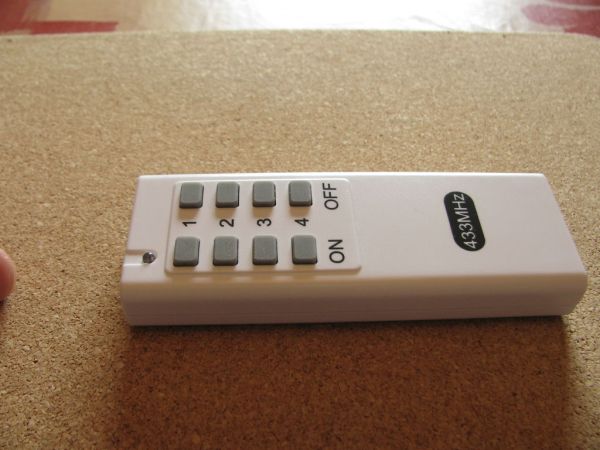
Essentially the RF remote will still be used to control the sockets, it’s just that, rather than pushing the buttons like some sort of Neanderthal, it will be controlled by the arduino (which is in turn controlled by the touch screen on your iPhone).
To do this we will need to take apart the remote.
First, remove the battery cover, which will reveal one of the six tabs that hold the front cover to the back of the remote. Using a flat blade or a small flat head screwdriver you can now pry this apart. I ended up loosening a couple down the side first as I found it to be easier but this might not be the case for everyone.
Roughly 25mm from the bottom of the remote and 35mm from the top there are tabs on either side. Again, taking your prying instrument of choice, slide it down the small groove between the top and the bottom of the remote’s casing and push these tabs until they come free. You may need to apply some levering pressure to get them to pop out properly.
Once you’ve done both the tabs on one side it should be much easier to release the tab in the battery compartment.
I found that loosening the tab at the top was now fairly simple (again push it with the blade or screwdriver until it pops free). I had to use a fair bit of levering pressure for this one.
Now you can just push the top of the casing against the bottom and the two tabs on the other side should pop free. If not, just repeat the initial process on the other side and you will have the top free (take a look at the photos which show where the tabs are if you’re in any doubt).
You can now just pull out the circuit board. Huzzah!
Step 3: Connecting the remote to the arduino
We now need to solder three wires on to the exposed circuit board. One 5V, one ground, and one data control. The 5V and Ground go to the appropriate sides of the battery holder (the side with the larger spring is the ground side and the smaller side is the 5V side).
I was initially concerned about losing range if I used a 5V supply rather than the 12V the battery it was designed for but I haven’t found this to be an issue. If you do decide to use a separate power supply, make sure to connect the power supply’s ground to the ground pin of the arduino else the data connection won’t work (they both need the same 0V reference)
The data wire must be connected to the Dout pin of the chip (see pictures). There is a resistor which has one side directly connected to the Dout pin (see pictures). I found it much easier to solder my communications wire to this than to the chip itself. It doesn’t matter which pin on the arduino it goes into provided you change the code accordingly. I used pin 10 and as such that’s what the code will have as a default.
Congratulations! The arduino is now connected.
Step 4: Setting up basic appliances ready for use
If you want to turn on things like TVs, speakers, lamps etc. then you can use the plugs you’ve already got!
Simply select which group and which channel you would like the device to have assigned to it on the back of the plug. You should note that there are a maximum of 16 possible separate plugs (four channels within four groups). You might want to consider limiting yourself to 12 as this will leave one full group free for your next door neighbour to use without them accidentally turning on and off your appliances and vice versa.
You will almost certainly want to keep a record of which appliance has been given what group and channel as you will need this later (I’ve got a big spreadsheet with all the information I need to program this stuff – more on that later).
To select the group and channel turn the upper and lower dials on the back of the plug (the upper dial is the group and the lower is the channel).
Plug the RF receiver into a wall socket and the appliance into the RF plug. Your appliance is now ready to be controlled by your arduino!
If you don’t want to turn on the main lights in your house (or you don’t fancy messing around with light switches and mains voltage electricity) then you can skip the next two steps.
Step 5: Taking apart the RF wall sockets
We’ll need to take apart the RF wall socket to get to the innards that will be used to control the main lights.
First use a flat blade to prise off the ring around the prongs (there are some half exposed screw holes just underneath that make this very easy). The ring is connected at the two lower bulges and at the top. Use the blade to free it from the two lower bulges and then you should be able to pry it off with your hands.
Now the two screws are exposed (they’re in the holes). The screws are a security Torx T15. I used a small flat head screwdriver that I didn’t mind damaging to break off the security spike in the screw and then a standard Torx T15 screwdriver to remove the screws. I would highly recommend using the correct screwdriver though to avoid quite a lot of frustration!
Once you’ve undone the screws you should be able to open the bottom of the socket. The top is clipped by two small plastic tabs. Lifting the bottom should cause the top just to pop out. If you’re really worried about damaging the enclosure you can use a blade to push the tabs in and release the top that way.
The part we’re interested is in the the part connected to the small circuit board. DO NOT touch the screw in the plastic covering at the top left of the board! This is part of the antennae and moving it, even slightly, can have massive effects on the range.
You will need to detach the three wires from the three terminals (may be a different number for different countries: I would assume the USA would only have two). The easiest way to get to the thick wires is to undo the small screw on the right hand terminal (a small flathead should do the job). You can then use a flat blade to lift the top half away from the bottom half.
Next cut the wires away from the terminals (it’s best to try and keep as much wire as possible so cut as close to the terminals as you can). The released terminal is easy; the other two are fixed and a bit more fiddly.
You should now have the circuit board free from the enclosure.
On the back of the circuit board you will see the two five-element metal sections that are used to select which channel the board will respond to.
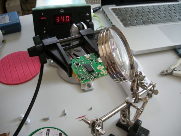
You will need to get or make two small jumpers. I just used a couple of very small lengths of wire with stripped ends. These jumpers need to be soldered on to the board to select permanently what channel the board will respond to. This can be quite fiddly and I found a circuit board holder (Panavise Jr) and helping hands/magnifier to be extremely useful here.
If you look at the back of the casing, the orientation of the numbers will be the same as the board flipped over (that is 1 and I on the far left, 2 and II at the top, 3 and III on the right, and 4 and IV on the bottom. Each centre point needs to be connected with one of the jumper leads to the appropriate surrounding point for the desired channel/group.
Congratulations! You how have the board setup to do your bidding!
For more detail: Home Automation (or Robot Butler called Geoffrey) – iPhone controlled, arduino based