The aim of this instructables is to share the parts and process of creating this device in the hope that it will get shared and improved to become something beyond my current imagination! I also have hopes for it to allow one person to enable another through making this project and giving it away to someone who is experiencing vision impairment or loss, such as Low Vision.
This project has been developed during my final year as an Industrial Design Honours student at RMIT University, Melbourne, Australia. Special thanks goes to Dr. Scott Mitchell for the inspiration and technical expertise in helping form the code underlying the HPM and further technical debugging.
Its included functions are:
– Pause button that switches off the range finding sensor and motor.
– Potentiometer to control the maximum PWM output to the motor (0 – 255)
– Potentiometer to control the maximum distance detected by the ultrasonic sensor (2-200cm)
– Inverse mapping of range to motor PWM, i.e. as the distance detected is closer to the sensor the motor vibrates stronger.
A comfortable level of soldering skill and familiarity with electronics is helpful along with an understanding of the Arduino programming environment. If you’re just starting with electronics/arduino build this project on breadboard first! Head to Step 6 and Step 4 to review the code and schematics to get your head around it.
A user test video can be seen here.
Step 1: Shopping List
Note:
- Most components have been sourced within Australia, they also should be available online and accessible to many other countries.
- All costs listed are in Australian Dollars without shipping.
- Links will lead to where I sourced the parts.
- Also keep in mind these components may be found cheaper elsewhere with a bit of research… and maybe bulk buying.
- E-bay is also a good place to start with things like the batteries, arduino and potentially rangefinder if DX doesn’t ship to you.
- Student discount available in-store at JayCar Electronics within Australia.
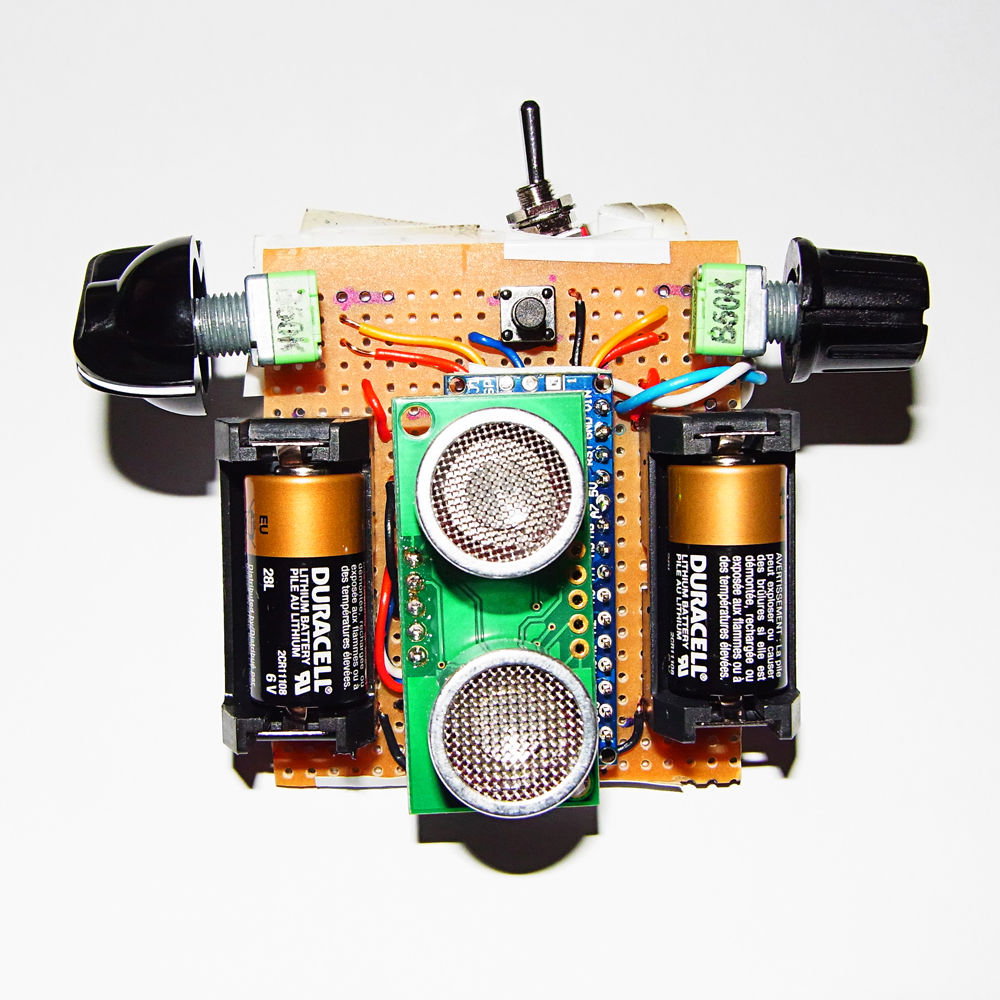
Pictured:
Strip Board [circuit mounting, jaycar electronics] (approx $6)
McDonald’s Straw [perfect diameter as a shroud to suit the vibration motor bellow] (free)
Arduino Nano v.3 (compatible) w.out headers soldered [sourced from ebay, but can be found on Deal Extreme] ($14)
Devantech SRF05 Ultrasonic Sonar Range Finder [distance sensing, from Robotgear.com.au] ($26) (Cheaper Options: HC-SR04 $4 from DX.com)
Female Header 1x4pin Straight 0.1″ [socket for ultrasonic sensor, from Robotgear.com.au] ($0.45)
Break Away Headers 40 Pins [Robotgear.com.au] ($1.75)
6mm Tact Switch [jaycar] ($0.95)
3V DC Vibrating Motor [Jameco part No. 256382] ($4)
Sub-Mini Toggle Switch [jaycar] ($2.45)
50k 9mm Square Potentiometer Linear Single Gang (qty. 2) [JayCar] ($2.75 ea)
Knobs (qty. 2) [jaycar] ($0.95 ea) pick something different/recycle old knobs if you have them
Economy Breadboard Jumper Kit – 5 Colours [jaycar] ($3.45)
Duracell 6V PX28L (2CR11108) 160mAh battery (qty. 2) [HollyHockBatteries.com.au] ($12.80 ea) (Cheaper option from Jaycar $3.25 ea)
Battery Holders pcb mount 1/2 AA (qty. 2) [RS Australia] ($3.95 ea)
Approx cost: $99.95 (+$50 for any further costs – generous estimation)
Approx with cheaper options: $56.95 (+$50 for any further costs – generous estimation)
Not Pictured:
Heat Shrink ($various)
Solder ($various)
Isopropyl Alcohol (pads from Jaycar $4.95)
Wire for proximity sensor
Masking Tape
Electrical Tape
Velcro Cable tie (in a small roll – this part is optional see optional step)
Tools:
- Soldering iron and equiptment
- Third hand
- Coping saw or bandsaw
- Pliers
- Plastic cutting tool
- Scissors
- Permanent marker
- Mini flathead screw driver
- 1.15mm drill bit
Step 2: Board Prep, Layout and Cutting
- The battery holder has a little plastic nodule that needs to be trimmed off, do this with the plastic trimmers.
- Layout 2 x 9mm Pots, 1 x arduino nano, 1 x tact switch, 1 x 1×4 header, 2 x battery holder on the non-copper side of the strip board.
- When you’re happy with this, mark it out using the permanent marker. Also mark-up the cutting outline – leave one or two rows of holes away from where you’d actually want to cut, depending on how you cut the board it may shatter. If you’re more confident you can get a precise cut go for it!
- Use the coping saw to cut up the board.
- Drill out the holes where the battery holder will go into as they are slightly larger than the strip board holes.
- Clean up the copper surface with isopropyl alcohol
Step 3: Prep the Sensor
Tips:
- Place heat shrink over every second wire before heat shrinking the whole connection.
- Depending on how you’ve connected the arduino pins to the 1×4 female header, solder the relevant wires on the sensor to that of the male header. I.e. Trigger on sensor to trigger on arduino. This will mean you can just plug straight in.
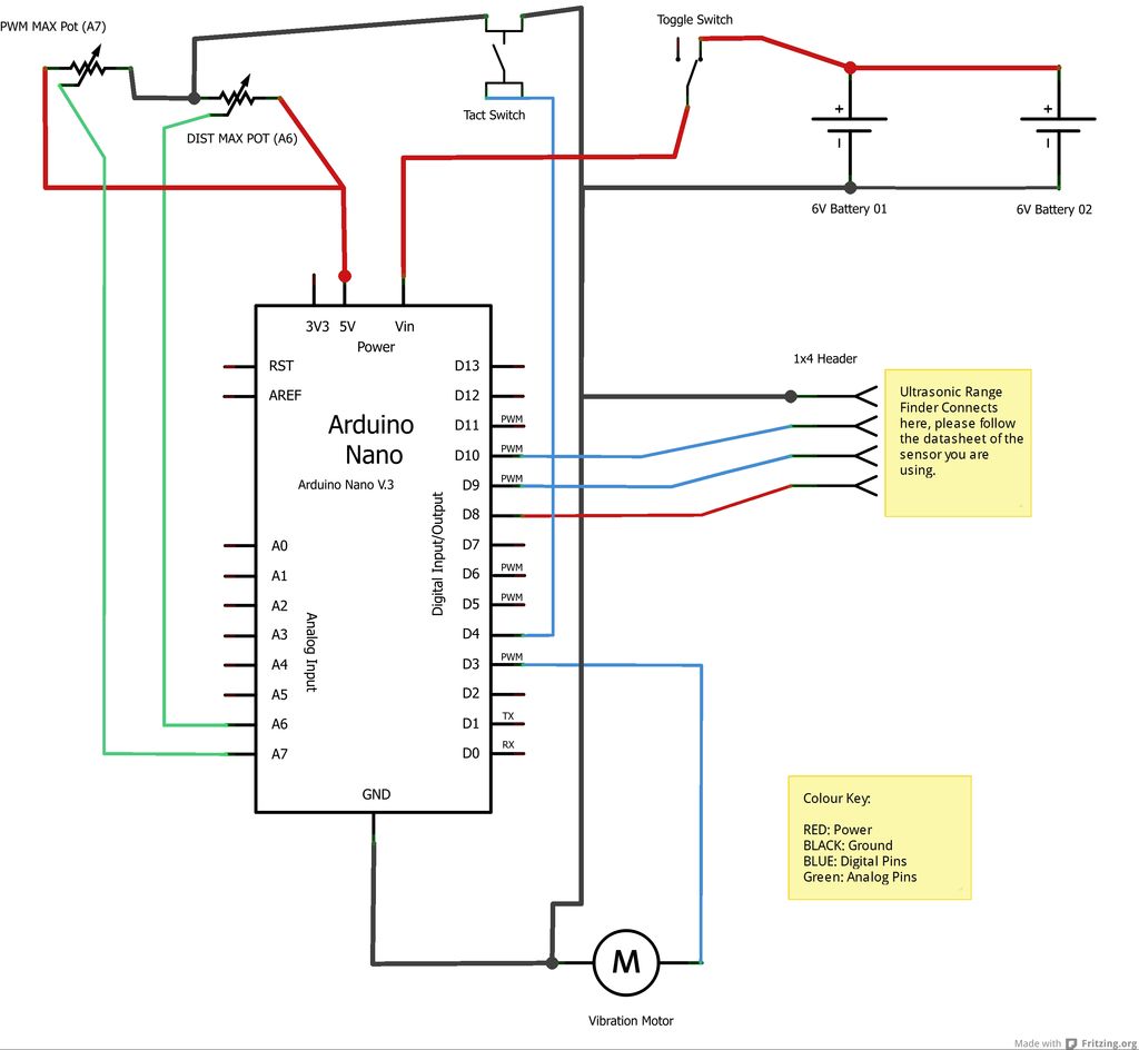
Step 4: Solder up the Board!
If there is any confusion regarding the circuit layout please comment bellow. I have included the Fritzing file [zip], schematic and strip board diagram. The fritzing file should help you investigate the layout much closer – I attempted to replicate the layout on strip board also, despite best intentions, this is messy. Also I have used 9V batteries in the layout diagram as there are no 6V batteries in frizting – the 9v batteries will work fine but they will not fit on the board (unless you get creative…).
Order of soldering:
- Arduino Headers on to the board (it is important that the arduino is NOT attached to the headers), note: it is best to solder the short end of the header through, in case you need extra height between the arduino and board to clear any jumpers.
- The pots and tact switch on – note that the position is different from the marked position in the previous step.
- Battery holder and 1×4 straight header
- Once this is done mark out where the jumper cables will be soldered.
- Jumper leads:
- Solder 1×4 straight header to digital pin 8,9,10, GND (VCC, Echo, Trig, Ground)
- Battery Holders – in parallel, ground to ground, positive to positive – make sure that this strip is empty and only batter power runs on this.
- Tact switch ground and digital pin 4
- Potentiometers: as they are on a common strip with the tact switch ground this part is done. Solder one pot to Analog pin 6 (A6) and the other to 7 (A7). Solder the voltage to 5v.
- Solder two wires onto the toggle switch, this will be used to bridge the battery positive strip with the VIN pin on the arduino. Put some heat shrink on to the switch’s terminals.
- DC Motor:
- to the rear, directly on to the copper, blue to GND and red to Digital pin 3.
- Cut McDonald straw to length and then tape it on, making sure you cover the rotating part of the motor with enough straw.
To finish the circuit you will need to break up connections on the strip board. There are two ways to do this, the messy way and the clean way. This is the messy way:
- Once everything is soldered, mark out with a permanent marker where the breaks need to happen.
- Proceed to cut the breaks in with a pair of plastic trimmers, some areas will be tricky and delicate – carefully use a sharp blade for this.
 HPM_Fritzing file.zip979 KB