How to modify a guitar tuner so it can be used by a blind person
This build uses an Arduino Pro mini microcontroller, (all code is provided).
This project was undertaken for the charity Remap, which provides custom-made equipment for people with disabilities.
Summary
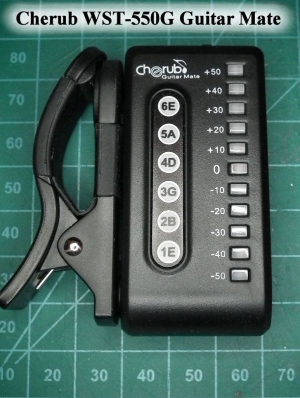
Begin with an LED electronic guitar tuner. I used a Cherub Guitar Mate (WST-550), which cost about £10 from eBay. It was a good choice for this project as it worked well and, as it uses through-hole LEDs, it was quite easy to solder to.
Use a microcontroller (Arduino) to read the LED’s then output the information as a series of tones through a headphone.
Using the tuner
When it is turned on, the tuner will play a scale to let you know it’s on.
If the tuner is set to semitone tuning mode it will play 4 low-frequency flat tones.
When a guitar string is sounded, the tuner will play the note it believes the string is playing before either playing three sharp or three flat tones, depending on whether the string is sharp or flat.
The duration of these three tones will depend on how sharp or flat the string is (long tones if the sounded string is very out of tune, short tones if it is nearly correct).
If the string is in tune, the tone associated with the string will be repeated.
A specific string can be selected by pressing the button on the back of the tuner, the tuner will cycle through the strings to be tuned. It will then only give feedback tones (as in default mode, above) once the correct string is played.
Step 1: Dismantle the guitar tuner
To dismantle the guitar tuner remove the battery and battery holder.
Undo the two screws on the back of the tuner and gently prise the two halves of the case apart (I used my fingernails).
Step 2: Make some space
In order to make some space in the guitar tuner, you’ll need to do the following:
Modify the plastic case
I used a knife, some small files and some wire cutters to clear space for the Arduino in the back of the guitar tuner.
One of the screw holes in the case will need to be removed, as well as some of the plastic that holds the battery in place.
Modify the circuit board
Remove the black foam battery pad and de-solder the battery contacts. Some of the through-hole components may have wires sticking quite far out of the back of the board, so tidy them up and clip them down to make as much space as possible.
Step 3: The circuit
In order to use slightly fewer Arduino input pins, some of the very high and very low tuner signals were combined with diodes.
See the picture for how to construct the circuit…
The other additional components (headphone, button etc.) will be discussed in step 5.
Step 4: Add the Arduino
Solder the arduino to the back of the guitar tuner circuit
To insulate the Arduino from the guitar tuner circuit, I used a piece of plastic from some packaging and held it in place with a sticky foam pad.
This build uses up most of the Arduino IO pins (even the analogue inputs have to be used as digital inputs).
I found that fairly thick enamel copper wire was the easiest to use for this job; its insulation can be melted off using a soldering iron. However, it’s best to use plenty of fresh solder. Starting from the open (cut) end of the wire also seems to help.
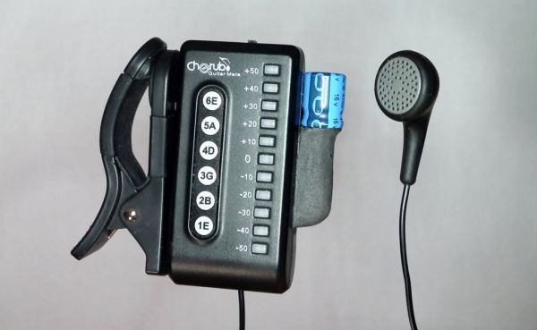
Step 5: Add the backpack
Some of the components won’t fit inside the tuner casing. So I put the battery, button, power-smoothing capacitor and headphone on the back of the tuner.
I made the backpack arrangement detachable from the main circuit so that I would still be able to open the tuner for re-programming if required.
Feedback problems
A resistor has been put in series with the headphone; it can’t be seen on these pictures as it is surface mounted and located under the circuit board. Use the highest value resistor you can that will still give loud enough tones.
Using a large-value resistor and a big power capacitor helps prevent the output tones from interfering with the tuner; if this happens, it can cause it to interfere with itself and go a bit mad.
I used a 470uF 16V capacitor and a 470Ohm resistor. However, you may need to experiment in order to find what works for you.
Capacitor placement
If the capacitor remains permanently charged (that is, if it is in the circuit before the power switch) it may be bad for battery life as it will have a leakage current.
For more detail: Guitar Tuner for the Blind (using an Arduino)