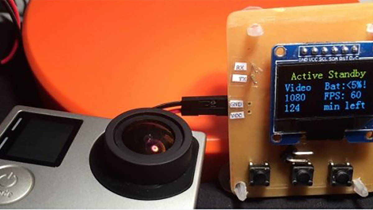
In this tutorial, you will read about all the steps, how to get to your own cheap and powerfull GoPro remote.
YOUTUBE VIDEO WILL FOLLOW SOON!
- Preparation
- PCB creation (printing / sawing / etching / drilling)
- Soldering
- Programming
- Having fun
- Support me by following, thx!
Preparation
Do you have all these parts at home?
- one sided PCB plate for etching
- safety glasses and gloves
- 50g sodium persulphate (N06CG)
- some pin headers
- 1x 6 pin OLED Display (GND, VCC, SCL, SDA, RST, D/C)
- 3x pushbuttons
- 1x ESP8266 ( I used the 07, but 12 should work aswell)
- 3 x 33kOhm SMD resistors
- 1x AMS1117 voltage regulator 3,3V
- 1x USB to TTL converter
- some jumpercables for programing
- soldering iron (if you dont own one, stop reading here, close this page )
- plastic vessel for etching
- a piece of a glossy magazine
- Laserprinter
- Laminator or Iron
- scissors
- little boards saw
- 0.3 mm PCB drill
- drilling machine with stand
- spirit or alcohol
- rough sponge
PCB creation
Print this PDF (ESPGOPRO_etch_copper_bottom) on a glossy piece of magazine – I have cut out a squere piece 10 x 10cm and taped it in the center of a sheet printerpaper.
Water the sponge with alcohol or spirit and scrub the copper layer of the PCB.
Cut out this printed (yes it is mirrored, it has to be!) only so etch template and tape it with the printed side down to the copper sided PCB.
You can now saw the needed piece of the PCB. What a mess. Puhhh.
Now heat up your laminator / iron and burn the laserprinted pigments onto the copper of PCB. I let it run through the laminator for 10 times at 125 °C.
5 minutes under the iron should be okay. But without steam!
Wash the paper off the PCB. It should look like this:
Put on the glasses and the gloves, if not: Do not keep going!
Fill in the vessel 100 ml of 50 °C warm water and give 20 g of sodium persulphate.
Place the printed PCB in the center of the vessel and swing it a little. This step took nearly 1 hour, to dissolve the not printed copper:
Wash the thoroughly under cold water:
Take the drilling machine and your thin drill and drill the holes for the Pinheaders of the OLED Display and the buttons. This where 18 holes. If you want – you can drill some holes for extra pin headers ( GPIO 0 to GND jumper, GND VCC and RX TX for programming.)
You must not drill the extra holes, you can solder some wires to the contacts, or put them to te down side of the PCB directly. I drilled them.
Read more: GoPro Remote Control V2

