In the kingdom of rock and roll it is important to set oneself apart. With millions of people in this world who can play the guitar, simply playing well is just not going to cut it. You need something extra to rise up as a rock god. Consider this guitar the mystical glowing ax bestowed upon you by the Rock Goddess of Bangs; The fabled ax that will lay waste to nonbelievers and shred through the aether with the transcendent glory of rock. With this weapon of unfathomable power, you will be an explosion of light and sound rising up above the writhing masses.

While there are a couple of other glowing guitars out there, this one by and large sets itself apart. For starters, it is frosted to diffuse the glow of the LEDs. This means that the whole body glows instead of being just edge-lit, and you can also see it during the daytime. The other unique feature of this guitar is that it responds to the music being played. The brightness is adjusted by the volume, and the color is controlled by the duration that it is being played. So, the harder you rock, the more colors you will see.
Step 1: Go Get Stuff
You will need:
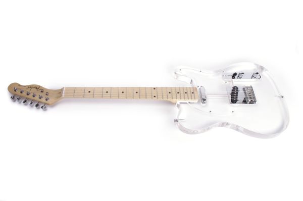
(x1) Clear acrylic guitar (search Google)
(x1) Arduino Micro (Radioshack #276-258)
(x1) Addressable 3-color LED strip (Radioshack #276-339)
(x1) LM741 op-amp (Radioshack #276-007)
(x2) 2N5457 transistors — alternate: NTE457 (Radioshack #55050922)
(x1) 10M resistor (Radioshack #271-1365)
(x2) 2.2M resistor (Radioshack #55049482)
(x1) 470K resistor (Radioshack #271-1133)
(x4) 100K resistor (Radioshack #271-1347)
(x2) 47K resistor (Radioshack #271-1342)
(x2) 10K resistor (Radioshack #271-1335)
(x1) 1K resistor (Radioshack #271-1321)
(x1) 10uF capacitor (Radioshack #272-1025)
(x2) 1uF capacitor (Radioshack #55047773)
(x3) 0.1uF capacitor (Radioshack #272-135)
(x1) 1N4733A zener diode (Radioshack #276-565)
(x1) PC Board (Radioshack #276-150)
(x1) 6′ mono audio cable (Radioshack #42-2472)
(x2) 4 x AA battery holder (Radioshack #270-391)
(x1) M-type power jack (Radioshack #274-1582)
(x20) 4-40 x 1/2″ bolts
(x1) 6″ x 6″ x 0.025″ glossy stainless steel
(x1) 2-part epoxy
(x1) 12″ x 24″ x 1/6″ sheet of acrylic
(x1) electric guitar string set
Step 2: Unstring the Guitar
Wind down each of the tuning machine heads and remove all of the strings.
Step 3: Take of the Neck
Detach the neck from the body of the guitar by removing the four screws at the base of the neck.
Step 4: Remove the Control Plate
Unscrew the control plate from the body of the guitar.
Make note of where the wires from the pickups and output jack are connecting to the controls.
Once you are sure you have a record of the wiring connections, cut the wires to free the control plate entirely from the guitar.
Step 5: Remove the Bridge
Remove the screws holding the bridge to the guitar body, and free it from the guitar.
In my case, one of the pickups came along with it. If you have a guitar in which the pickups are not attached to the bridge, remove the pickups seperately.
Step 6: Remove the Jack
Remove the output jack from the guitar body.
Step 7: Remove the Pickguard
Remove the screws holding the pickguard to the guitar body and any of the remaining pickups.
Step 8: Detach the Strap Buttons
Unscrew both of the strap buttons from the body of the guitar.
The body should now have nothing attached to it.
Step 9: Cut
Cut the LED strip into a 16″ and a 20″ section (or however long you deem appropriate for your guitar).
Solder 18″ wires to both ends of the 16″ LED strip.
Step 10: Route
Using a router table, make one channel that runs between the strap button mounting holes that is 20″ long, by 0.25″ deep, by 0.6″ wide.
Next, make another channel that is 16″ long by 0.25″ deep by 0.6″ wide that starts at the edge of the audio jack mounting holes and runs the legnth of the bottom of the guitar.
These channels will hold the two LED strips. Thus, if your LED strip is longer, you will need longer channels.
Step 11: Drill
Drill a 1/4″ diameter hole from the edge of the routed LED channel that is closest to the control comparment down on through the side of the guitar into the compartment itself.
Drill another 1/4″ hole from the back side of the guitar straight down until it intersects with the opposite edge of the same routed channel.
Drill a similar 1/4″ hole to meet the closest edge of the other routed channel.
Step 12: Trace
Place the battery holders and circuit board on the back side of the guitar in a spot where there is room to route a channel large enough to fit both battery holders and the circuit board.
In my case I found they fit upon the back side perfectly between the two pickup channels.
Step 13: Route
Using a straight edge clamped to the body of the guitar as a guide, follow along the perimeter of the tracing with a plunge router. This will require readjusting the guide for each face of the perimeter.
Once the perimeter is cut, route out all of the material that is remaining on its inside.
This should approximately leave a 6.25″ x 2.85″ x 0.65″ rectangular electronics compartment.
Step 14: Wire Channels
Route two straight channels that are approximately 1/4″ wide by 1/4″ deep from from each of the 1/4″ holes drilled in the back of the guitar to the electronics compartment. These channels will be used to route the wires connecting the two LED strips.
Step 15: Insert the Strip
Take the wires connected to the one LED strip and pass them through the long 1/4″ hole that goes into the control compartment. Pass the other set of wires through the 1/4″ hole that goes out the back of the guitar body.
Pass the wires that have come out the back through the other 1/4″ hole into the other LED compartment.
Solder them to appropriate terminals on the other LED strip such that the two strips are wired in parallel.
Step 16: Cut, Bend, Glue and Clamp
Cut a 20″ x 0.6″ strips of 1/16″ acrylic, and also a 16″ x 0.6″ strip of 16″ acrylic.
Once you have the two strips, now comes the tricky part.
Lay the LED strip flat in each of the channels and clamp the edge of the acrylic strip to the inside edge of the channel of equal legnth, and then epoxy the corner of the strip in place. Place a clamp on this corner.
Using a heat gun, soften the strip and form it around the counter of the guitar. Epoxy and clamp the strip in place as you go, until it is clamped in the channel and neatly epoxied in place.
Wait for the epoxy to fully set and repeat this process with the opposite channel.
Of course, this is easier said than done and make take a few attempts go get right. One thing I encountered while doing this is that the clamps tend to slip, especially when there is wet epoxy around. I solved this by placing a few thing pieces of scrap wood over the acrylic and then clamping it. This provided just enough traction to keep it from slipping. However, be careful not to get too much epoxy on the wood or you will have an annoying time sanding this away later.
Step 17: More Routing
Using a 3/4″ diameter plunge router bit, cut a 1″ wide by 1″ deep channel for the power switch.
Flip the guitar over. Using the same bit, and at the same depth as the electronic compartment, make a notch off one edge large enough for a power charging jack to fit.
For more detail: Glowing Color-Changing Guitar