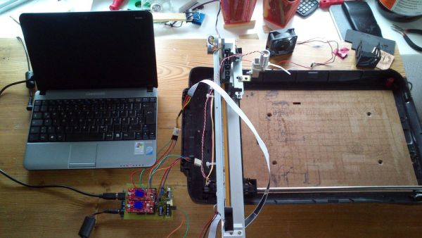
This Frankenstein Laser Cutter was built out of an old scanner and printer.
The whole thing evolved around the instructable of Groover and his ‘Pocket Laser Engraver’.
This is a Making-Of. Although a lot, if not everything, of the mechnical construction requires ingenuity I tried to document the complete build process as much as I could. Every scanner and printer mechanics are different so this could not be used as a step-by-step guide. More of a “how it can be done”-guide. I try to cover the questions that could arise in the process of making.
 I had absolutely no clue about electronics. All I knew was that RED is (often) + and BLACK is (often) Ground.
Therefore I have learned a lot in this project. Starting from mechanical stuff like self-replenishing brass bearings to electronical stuff like stepper motors and the difference between bi- and unipolar motors to soldering and etching my own board.
The work area is 270mm x 200mm. Just about right do cut some flip-flops for the summer.
It is able to cut :
- foam rubber
- tape
- vinyl
- paper (nearly every color but white/red)
- several plastics (could require several runs depending on thickness)
It can engrave:
- light wood (Balsawood/Poplar)
- leather
- bone
- horn
- plastics
- some varnishes
- blank cds/dvds (purple/blue)
The color is quite important. White and in general bright colors are hard if not impossible to work with.
Those colors reflect the red laser beam to much.
Red(ish) colors are a problem as well as they reflect all light in the red range spectrum.
The building costs (without mispurchase [easydriver clones were for the trash can]) is around 45-55 €.
| Arduino(clone) | 10 € |
| Easydriver x 2 | 20 € |
| Electronic bits and pieces | 10-15€ |
| Aixiz housing /w lens | 6 € |
| Alu-profiles | 5 € |
| ————————————- | ———- |
| Total | 46-56€ |
Well I forgot the Laser Safety Glasses (THIS IS A MUST!!):
— SEE STEP 16 FOR LASER SAFETY GLASSES —
| Laser safety glasses | 50 € |
| New total | 100 € |
Build time with knowledge acquisition and waiting for shipping was around 4 month…
I am constantly updating this so be sure to come back from time to time for further improvements.
UPDATES:
May, 9th 2013 : Updated Step 14 : The Laser diode (pictures and some focus hints)
Added Step 18 – Take it to the next step (Improvement – optional)
Updated BOM list. Now contains more stuff you need
May, 20th 2013 : Corrected mm/sec to mm/min ! Seconds would be very very fast.
June, 1st 2013 : Added Step 13 – Alternate laser driver shield (Easylaser Shield)
December, 4th 2013: Updated Alternative Easylaser Shield schematic/layout with the help of jduffy54.
Step 1: Indentifying the salvage loot
Before you go an a salvage rampage consider the following hints:
RULES OF THUMB
- The older the printer the better.
- The newer the scanners the better.
Scanner stepper motors are often superior to printer steppers. They do have more steps in general.
The newer the printer, the lesser is the chance of getting steppers out of it.
All scanners have stepper motors. The older the more likely you are getting a unipolar stepper which we can’t use in this project.
——————————–
Identifing the parts of old devices is often a pain but I had luck with at least the scanner stepper. For the printer I had found a service manual. But this didn’t helped me alot.
Scanner / X-Axis
The scanner is an old Tevion 2400 dpi scanner. Equivalent to a Microtek Scanmaker 5800.
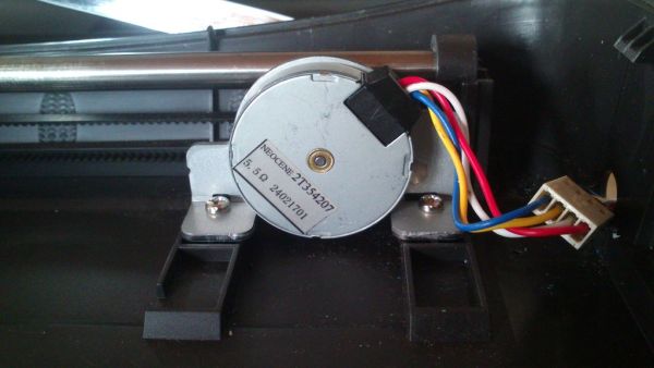
The stepper is a 96 step bipolar stepper motor. It’s description is NEOCENE 2T354207.
Do not believe anyone other that says this is a 100 step motor. It is not ! It has 96 steps. Not more not less.
I used the bed of the scanner as the basis of the whole construction.
The rail and the timing belt aswell as the sled which carried the photoelectronics is used.
Though the sled needed to be trimmed to give more space for the laser.
There is something special about the stepper. It has a 4 gears mounted on its foreplate.
The gear ratio is luckly negligible.
If you are still curious how to calculate a gear ratio have a look at this page.
It is in german but the math shown there is a universal language (or use the google translator)
The scanner stepper serves as the x-axis.
Printer / Y-Axis
The printer was an old Epson Stylus Photo 925.
The stepper I salvaged is oddly described in the Service Manual.
It says it is a 4-phase 48 pole bipolar stepper motor for 42V (??) but as it is a bipolar stepper there must not be 4 phases but 2.
Turning the shaft by hand and counting the steps I came up with 48 steps.
This motor (and plates for printer head) serves as the y-axis.
In the end I realized that the 48 steps or the motor itself are the weak spot in this built. It moves slower than the scanner stepper and clatters on the rod. No brass fittings here. Vaseline should dampen the negative effect.
Stepper motor specifications:
| Tevion 2400 dpi / Microtek 5800 | Epson Stylus Photo 925 | |
| Phase | 2 | 2 |
| Step angel | 3,75°/Step = 96 steps | 7,5°/Step = 48 steps |
| Voltage | 5 V | 5-12 V |
| Current | ? | ? |
| Resistance | 5,5 Ω | 7 Ω |
| Holding torque | ? | ? |
Later in the process I found out that both motors draw less then at least 300 mA.
The Easydriver V4.4 still has the bug with the silk print on it mixing MAX and MIN of the poti.
So in V4.4 they switched the print on the PCB but simultaneously replaced the poti with a reverse poti.
At least this is what I have read in some forums or the comments over at Sparkfun.
Smart 🙂
So long story short:
The poti is set to a low resistance that means the steppers get a fraction of the current the Easydriver can deliver. Max 750mA per coil. The poti is set to roughly 25%. Just so that they dont scream in pain.
Stepper motor pinout:
On my journey through the endless deepth of the internets I often stumbled over question as how to get the correct pinout from the steppers.
You just need to take a piece of wire and connect the pins. If you connect the correct pairs you should feel a resistance when turning the shaft of the stepper
Step 2: Scanner massacre
As I guess you don’t have the exact same old scanner and printer this step is more like a rough lineout of what needs to be done and what must be cared for in special. Different scanner or printers have different mechanics but all in all they have similar structure.
I reused the bed of the scanner and its slide that contained the photo-electronics. All the electronics and glass mirrors where removed. Use a screwdriver and wear protective gloves.
So in the end just the bare plastic remained and afterwards was cut into form to have a slightly wider space for the printer head carriage which later carries the laser module with fan.
Step 3: Printer mayhem #1
This was the most tedious step in the whole project. Took me about complete 8 hours to complete with the help of an advanced craftsman (Father).
The plate of the printer which supported the print head and rod was excessively treated with my beloved metal saw.
I had to cut out pieces of the L-profile to get room for the stepper.
In the original printer structure there was a DC motor where now the stepper resides. Often (hopefully) the washer of the stepper, which is from the same printer, has the same spacing so it fitted nicely into the DC hole.
Step 4: Printer mayhem #2
The rod on which the led the print head carrier had some decentered metal nobs on it. They could we easily removed by twisting them and pulling them off with a plier. They revealed very nicely centered metal tips.
I used two T-profiles and drilled holes in them. So I could just plug the tips from both end through and mount both profiles on the L-profile. This step needs to be precise as possible as later on the y-axis might drift off. This might distort the whole drawing/lasering process as the Y-axis isn’t right-angled to the X-axis. Use a caliper is a must. Drawing by eye, too.
Step 5: Cabeling #1
Y-axis cables
As the motor moves with the Y-axis (obviously) I had to think about how to do the cabeling.
I used an salvaged 5-pin connector from an old mainboard and simply soldered it to the stepper motor wires. A 4-pin ribbon cable served as an extension to a little piece of stripboard which I mounted to the L-profile.
The stripboard is a “gateway” for all electronics on the movable Y-axis to the arduino.
I took the flat cable which used to be connected to the scanner sledge and soldered some female pin headers to it. Very crude job with room for improvement. If I would have been more cautious I could have soldered 8 pins to the flat cable but this is a very fragile task. You will see why later.
For more detrail: Frankenstein Laser Engraver