Fluid In.Flux is a 3D printing experimental machine which prints wax in water. The Machine was a semester-wide exploration as part of the Advanced Architecture Studio called “Creative Architecture Machines” by Professor Jason Kelly Johnsonand Michael Shiloh at the California College of the Arts, in San Francisco.
 Fluid In.Flux is about exploring material behavior in different conditions and developing an innovative method of digital fabrication. The project aims at abstracting the input geometry and creating imprecise abstract forms through precise machine operations. These imprecise abstractions are the result of the material system of the project. The material system involves the articulated ejection of hot liquid wax in cool water, taking advantage of wax’s buoyancy, rapid phase change and wax’s ability to fuse and bond to itself and other materials. Water is used as a catalyst to solidify wax rapidly and fabricate additively in the process.The scope of the project is a form generator, to develop digitally controlled construction systems. Projecting it onto an architectural scale, autonomous machines can be deployed onto fresh water basins to create buildings, cities possibly, under water opening up to a wide range of potential applications.
The machine was designed, assembled and calibrated by Architecture students at California College Of The Arts – Darshini Shah, Ibrahim AlGwaiz and Swetha Kopuri. Please feel free to contact us with any comments, questions or feedback. Happy to share and help!
Step 1: Building the machine
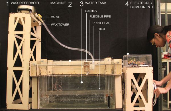
1. The machine essentially has 4 components –
1.1 Wax Reservoir and Tower
1.2 Machine Armature – 1/4″ thk Plywood
1.3 Water Tank – 1/4″ thk Acrylic
1.4 Electric Components and Tower.
Step 2: Making the Machine Armature
1. Laser cut the following components out of 1/4″ thk plywood.
2. Follow the diagram for assembly.
3. Zip tie the plywood components of the machine.
4. Insert the stainless steel rods into the prescribed holes in the plywood components. While inserting the rods, at appropriate points, fix the gears onto the rod using a ranch.
5. After the armature of the machine has been fixed, position the timing belts accordingly.
6. The prescribed motion is therefore produced by powering the Stepper motors, that directly bring about rotation in the gears, that in turn displace the respective components such as either the Gantry, Print Head or Bed, through the interconnecting Timing Belts.
Download Rhino File Below
https://www.dropbox.com/s/r7jjo0o5bvyzqpi/Fluid%20In%20Flux%20-%20Rhino%20Model.3dm
For more detail: Fluid In.Flux_3D Wax Printing In Water