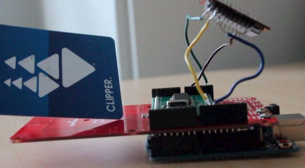
Music party is a new way to listen to music with others. By tapping an RFID/NFC device that is synced to a Facebook account on an Arduino RFID reader shield and sending that unique ID to Music Party server using the Arduino WiFly shield, we can automatically listen to the favorite music of everyone who taps in. Go to the Music Party website to see an example.
About Lifegraph Labs
My name is Jon and I’m a member of Lifegraph Labs! We’re a group of six students at Olin College of Engineering passionate about connecting digital and physical interactions. We have a website with a handful of how-to’s and tools you can use to connect to the internet, and leverage information about your digital identity. Check out the website and our Github repository! All the code for this tutorial can also be found on our Github repo.
What you’ll need to make Music Party:
[box color=”#985D00″ bg=”#FFF8CB” font=”verdana” fontsize=”14 ” radius=”20 ” border=”#985D12″ float=”right” head=”Major Components in Project” headbg=”#FFEB70″ headcolor=”#985D00″]
A Computer
An Internet Connection
An Arduino
Adafruit NFC/RFID Reader Shield or Sparkfun RFID shield (& Stacking Header Pins to connect to the Arduino)
WiFly Module
An NFC/RFID device (Any 13.56 MHz RFID card will work). You can see an example here.
A Facebook account (that has ‘liked’ bands/music)
[/box]
One more Note: We’ll guide you through how to do this with the above mentioned Arduino shield/module but you can easily modify it to be able to work with a different RFID or WiFly solution if you already own one.
System Overview
Check out the block diagram image for a pictorial representation of the system or follow along with the video above.
It starts with the RFID reader reading the unique id of whatever device/card was placed near it (we’ll call this the Tap ID). The reader passes the Tag ID on to the Arduino which sends it and the Device ID (which you will make up) out to our Music Server through the WiFly module. That’s as much as you need to build! The rest has been extracted into a separate server that can handle everyone’s requests to remove a lot of the complexity. If you want to configure your own server you can check out the Github repository for it or let us know and we’ll make a tutorial for it!
The server will take care of converting the Tag into a Facebook ID, grabbing the musical preferences of that person associated with that Facebook ID, merging those tracks back into the playlist for everyone else in the room and passing those tracks to who ever connects to the URL associated with the Device ID (musicparty.herokuapp.com/*Device ID*/party). We are using the Tomahawk API when you connect to a music party in your browser to find a media source that can stream each particular track (youtube, soundcloud, etc.).
We built the Lifegraph Connect platform to have a centralized API and database for bridging physical and digital identities. It’s easy to use, and once we put the hardware we’ll sync our IDs there so that we can convert an RFID tag to a Facebook ID.
Now let’s get started with the tutorial!
Step 1: Set up the Hardware Stack
The first thing we’ll need to do is put out hardware together. If you haven’t soldered the stackable header pins onto your RFID shield, you should do that first. Lady Adafruit has a great video that explains how to do it for first-timers.
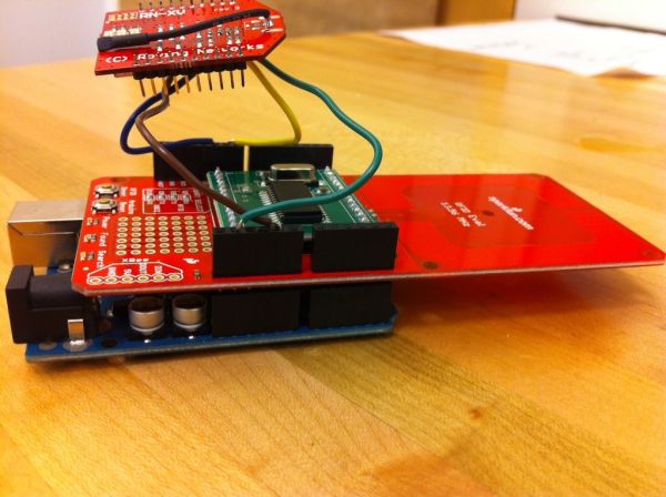
After you’re done soldering the stackable header pins to the shields, you’ll need to attach the WiFly module. We’ve made a whole tutorial dedicated to connecting the Arduino to the internet with WiFly but for the sake of this Instructable, just follow the section for soldering and connecting the pins into the shield. You can see a picture of the hardware stack below (with the Sparkfun board).
Step 2: Reading RFID Tags
Now we’ll need to set up our Arduino to read RFID tags. If you haven’t used Arduino before or you have trouble along the way, the Official Getting Started page is very useful. Connect your Arduino to your computer with a USB cable. If you haven’t already, you’ll need to download and install the Arduino developing environment.
We’ll also want to intall some libraries to make this coding less tedious. If you have Lady AdaFruit’s board, download the here and if you have the Sparkfun board, download the library here Store it in the Libraries folder of your Arduino (on OSX, the default directory would be ~/Documents/Arduino/libraries/ and on Windows, it would be My Documents\Arduino\libraries\) (if you have problems with this, check out Lady AdaFruit’s advice. If you already had the Arduino environment open before placing the code in the Libraries folder, restart it now.
Place the RFID Shield on top of the Arduino. Now we can get to the code. All the code you’ll need can be found here in our Github repo.
Create a new Arduino sketch by selecting the Arduino application and clicking the dog-eared paper icon, copy the code from the link above right in, and save it in your project directory. All you have to do now is uncomment three lines at the top of the file depending on which RDID reader you have.
If you have the Sparkfun sm130 RFID board, uncomment these three blocks:
// #include <SoftwareSerial.h>

// #include <sm130.h>

// NFCReader rfid(7, 8);
And if you have the Lady Adafruit RFID board, uncomment these three blocks:
//#include <Wire.h>

//#include <Adafruit_NFCShield_I2C.h>

//Adafruit_NFCShield_I2C rfid(2, 3);
The rest of the sketch is the same for both boards because we wrote the sm130 library to match that of the Lady Adafruit library. Now, click the right-facing arrow on the sketch to load the code on the Arduino and start running it. To see the output, open the serial monitor by going to File->Tools->Serial Monitor then make sure your baud rate is set to 9600 (the dropdown on the lower right of the serial monitor).
Now, if you tap your RFID card on the reader, it should print out the Unique ID! Awesome.
Now I will explain the code line by line if you’re interested, or else you can skip to the “Sending the UUID to the Local Server” section. Let’s start with the importing code:
// Uncomment these three lines to use the Sparkfun RFID shield

// #include <SoftwareSerial.h>

// #include <sm130.h>

// NFCReader rfid(7, 8);

// Uncomment these three lines to use the AdaFruit RFID shield

//#include <Wire.h>

//#include <Adafruit_NFCShield_I2C.h>

//Adafruit_NFCShield_I2C rfid(2, 3);

// The number of seconds to wait before accepting another tag

const uint8_t TIME_DELAY = 2;

// Var to keep track of time between tags

long lastReadTime = 0;
In this chunk we’re importing either the Sparkfun library or the Lady AdaFruit library depending on which one you uncomment. Sparkfun’s board uses the Software Serial (A.K.A. UART) for communication while the Lady AdaFruit board uses the Wire (A.K.A I2C). Then we make to global variables to keep track of the time between tags for later (to make sure it doesn’t keep reporting your tag over and over as you keep it close to the reader). Now let’s look at the setup method:
// Setup method is called once every time Arduino is restarted

void setup(void) {

  // Start communication with our serial monitor

  Serial.begin(9600);

  // Start running the RFID shield

  rfid.begin();

  // Print out a message to make sure Serial is working

  Serial.println("Initialized!");

  Serial.println("Requesting Firmware Version to make sure comm is working...");

  // Grab the firmware version

  uint32_t versiondata = rfid.getFirmwareVersion();

  // If nothing is returned, it didn't work. Loop forever

  if (!versiondata) {

    Serial.print("Didn't find RFID Shield. Check your connection to the Arduino board.");

    while (1);

  }

  // Got ok data, good enough!

  Serial.println("Found Version Data. Comm is working.");

  // Let us know RFID shield is waiting for a tag

  Serial.println("Waiting for an RFID Card ...");

}
In this first chunk of code, we add the ‘setup’ method which is a special method that only gets called once everytime the Arduino is restarted. In this method, we’ll start running Serial which is a communication protocol. Then, we’ll start running the RFID shield library itself. Next, we grab the firmware version just to make sure that our communciation with the board is working effectively – if not, we just loop forever. Now the looping method:
void loop() {

  // We will store the results of our tag reading in these vars

  uint8_t success;

  uint8_t uid[] = { 0, 0, 0, 0, 0, 0, 0 };  // Buffer to store the returned UID

  uint8_t uidLength;                        // Length of the UID (4 or 7 bytes depending on ISO14443A card type)

  // Wait for an ISO14443A type cards (Mifare, etc.).  When one is found

  // 'uid' will be populated with the UID, and uidLength will indicate the length

  success = rfid.readPassiveTargetID(PN532_MIFARE_ISO14443A, uid, &uidLength);

  // If we succesfully received a tag and it has been greater than the time delay (in seconds)

  if (success &&  (millis() - lastReadTime > (TIME_DELAY * 1000))) {

    Serial.println("Got a tag!");

    // Print out the length

    Serial.print("Length: ");

    Serial.print(uidLength, HEX);

    Serial.print(", ID: ");

    // Print the ID in hex format

    rfid.PrintHex(uid, uidLength);

    Serial.println("");

    // Same the last read time

    lastReadTime = millis();

  }

}
The loop method is called over and over again by Arduino. As soon as it’s code completes, it starts over. In our loop method, we create the success, uid, and uidLength variables to store the results of a discovered tag. We then attempt to read a tag, and if we do, the uid will be stored in the uid variable and the length of that uid will be store in uidLength. Then we simply print it out, and note what time it was printed out to make sure it doesn’t print over and over again.
Step 3: Connecting to the Internet with WiFly
Now we need to send out Tag ID to the server so it can keep track of who is listening to music on each device. We wrote an Arduino library to make web requests much, much easier that we’ll use. You can find all the code you’ll need here and we’ll explain the code line by line below. If you don’t want to read the explanation, just make sure you change the network authentication information so the WiFly can connect to your internet.
We’ve made a few additions to the previous RFID reading code. Let’s take a look at the new additions at the top of the file:
#include <WiFlyHQ.h>

#include <Lifegraph.h>

// Wifi Serial connection

SoftwareSerial wifiSerial(9,10);

// API we'll use to talk to the internet

JSONAPI api;

/* Change these to match your WiFi network */

const char mySSID[] = "YOUR_NETWORK_NAME";

const char myPassword[] = "YOUR_NETWORK_PASSWORD";

// The host server that handles our request

const char host[] = "musicparty.herokuapp.com";

// Unique ID of this Music Party Streaming Device

char deviceId[] = "YOUR_OWN_DEVICE_ID_HERE";
We added the WiFlyHQ and Lifegraph libraries to make connecting to the internet easier. The WiFly module needs to have a serial port to communicate with the Arduino with which we create on pins 9 and 10. Then we instantiate a JSON API (part of the Lifegraph Library) which wraps up HTTP calls into a few simple methods. We then provide our network credentials so that the WiFly can connect. The host is our own Music Party servers which handle all the http traffic. The last line defines the deviceId which you can make up. It will determine the URL of your music party so the more unique you make it, the less likely random people will be connecting to your music party.
Now let’s take a look at the new code in the setup function:
wifiSerial.begin(9600);

Serial.println("Connecting WiFly...");

  // Setup network connection.

  if (!connectWifi(&wifiSerial, mySSID, myPassword)) {

    Serial.println("Failed to join network.");

  } else {

    Serial.println("Joined wifi network.");

  }

// Create an object to send http requests

  api = JSONAPI(host, "", LIFEGRAPH_BUFFER, LIFEGRAPH_BUFFER_SIZE);
In this code chunk, we’re setting up the WiFly Serial communication and connecting to the WiFi. Then we create an API object to handle our HTTP requests to the Music Party Servers.
Now let’s look at the addition to the looping code:
// Start using the wifi serial so we can sent a request

    wifiSerial.listen();

    // Send the next post to the tap endpoint

    api.post("/tap");

    // Add the device Idparam

    api.form("deviceId", deviceId);

    // Convert the pId from uint8_t to a char so the server can understand it

    Lifegraph.stringifyTag(pId, pIdLength, pIdString);

    // Add the pId param

    api.form("pId", pIdString);

    // Send the request and get a response

    int response = api.request();

// Print out the response

    Serial.println("Server response: " + String(response));

if (response == 404 || response == 406) {

      Serial.println(F("Go to lifegraphconnect.com to sync device"));

    }

    else if (response == 200 || response == 0) {

      Serial.print(F("Go to http://musicparty.herokuapp.com/"));

      Serial.print(deviceId);

      Serial.println(F("/party"));

    }
Once we receive a successful tap from an NFC/RFID device, we start communicating with the WiFI board instead of the RFID board (wifiSerial.listen()). Then, we set the endpoint we are going to hit (which will always be ‘/tap’) and add the deviceId as a parameter of the request. Then we convert our pId from an array of uint_8 which looks like garbage when you print it out, to characters with the stringifyTag method. Finally, we send the request and check the response.
Put the code onto your Arduino, open up the serial monitor, and verify that you’re sending a request successfully. It should print out something like this:
Connecting WiFly...

Joined wifi network.

Requesting Firmware Version to make sure comm is working...

Found Version Data. Comm is working.

Waiting for an RFID Card ...

Got a tag!

Length: 4, ID: 0x88 0x04 0x16 0x34

open musicparty.herokuapp.com 80

Server response: 404

Go to lifegraphconnect.com to sync device
Great, now you’re ready to sync your digital and physical IDs!
For more detail: A Facebook-Connected, Arduino-Powered Music Party