The typical parallel LCD used with an Arduino (16×2 or 20×4) has 16 pins. Only 6 I/O pins are required on the Arduino, but what if you could get that down to two I/O pins, and still have those pins available for other devices?
The I2C interface is on pins A4 and A5 of the Arduino UNO. These are addressable, and are therefore shareable with other I2C devices that have different addresses. Now, you can buy I2C LCD’s, and you can even find I2C LCD’s with different addresses, but they are typically two line LCD’s, and the addresses are fixed. I’m going to show you how to build your own I2C interface, select one of 8 addresses, and even be able to add up to 8 inputs or outputs, using a MCP23017 16 port expander chip.This is the same chip Adafruit uses on their I2C LCD Keypad Shield, and uses their library to talk to it. You could even have up to 16 LCD displays, or up to 128 digital I/O pins, and combinations thereof
Step 1: LCD Wiring
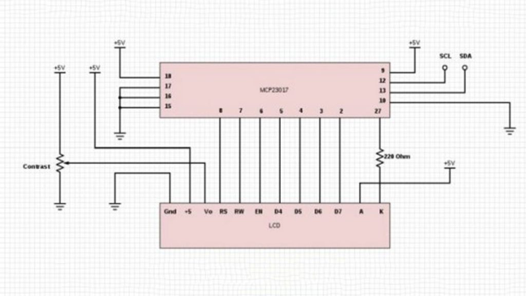
The connections between the Hitachi type parallel LCD (2 or 4 line) and the MCP23017 are shown in the photo.
SDA (pin 13 on the MCP23017) connects to Arduino A4, and SCL (pin 12) connects to Arduino A5. Some suggest 4.7k pull up resistors (pin 13 to +5v and pin 12 to +5v) but this project works fine without them.
Notice the 220 Ohm resistor on the LCD k (cathode, gnd) connection. This is a MUST!
Without it, you can blow the MCP23107 backlight pin. There are 3 pins you can use for the backlight. Pin 1 is called BLUE in the Library and Sketch, Pin 28 is called GREEN, and pin 27 is called RED. If you have a monochrome LCD, you can use any of the three pins, and use the corresponding color callout. If you have a RGB backlight, you can get many combinations of colors. Check them out at http://arduinotronics.blogspot.com/2015/04/arduino-ups-battery-shield.html
Pins 15, 16, and 17 on the MCP23017 determine the I2C address. We have all 3 grounded, as this is the default address the Adafruit library uses. To add multiple displays, or pick another address, the library will have to be modified, so we will go with the default for now.
Adafruit_MCP23017.h contains the following line:
#define MCP23017_ADDRESS 0x20
Pin 17 = A2, Pin 16 = A1, and Pin 15 = A0
0 = ground, 1 = +5v
The address format is 0100A2A1A0, so since we have grounded all 3 lines, we are using binary 0100000, or 20 in hex (0x20). 0100111 would be 27 in hex (0x27).
Read more: DIY I2C LCD Display