First off, why did we decide to call this thing SODAR? SOnic Detection and Ranging, or SODAR, is a lot like SONAR and RADAR. However, we don’t feel comfortable calling it SONAR because we have no desire to use it for navigation and we aren’t under water. Also, it’s definitely not RADAR as we are using ultrasonic pulses, not radio waves to find objects.
With the technicalities out of the way, here are the project’s objectives:
1) To create a freely rotatable SODAR system that can continuously detect objects
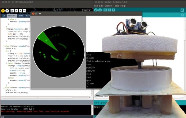
2) To create a UI that displays objects similarly to radar
3) To make it as portable as possible
To accomplish objective #1, we need a way to prevent wires from tangling while the motor spins. There are two ways that we thought would be relatively easily implementable. The first method would be to use two Arduinos and transceivers for a wireless transmission of data from the spinning platform to the computer for display. The other method would be to use something similar to a rotating electrical connection (REC), where the electrical connection would be maintained using a conductive liquid at the intersection.
While it seems to go against objective #3, we decided to go with the rotating electrical connection idea. This is mostly because we didn’t know if it’d work and wanted to try something new. On top of this, commercial slip rings are upwards of 20 dollars (price found by ellisgl) and we wanted to see how hard it would be to make a reliable REC. In our project, we are using a vinegar-salt solution as an electrical conductive liquid because it is functional and inexpensive.
Future Work Suggestion:
Use wireless transceivers so the project can be placed in one area and send data to the laptop in another area.
Collaborator:
Electrical circuit designer/builder extraordinaire: intensePancake
Step 1: Get Materials
[box color=”#985D00″ bg=”#FFF8CB” font=”verdana” fontsize=”14 ” radius=”20 ” border=”#985D12″ float=”right” head=”Major Components in Project” headbg=”#FFEB70″ headcolor=”#985D00″]
Non-electrical materials:
1) PVC couplings – 2″, 3″, and 4″ diameter
2) PVC Bushing – 1″X3/4″
3) Household Goop adhesive (water-proof)
4) Gorilla glue adhesive
5) Elmer’s glue adhesive
6) 12″ x 12″ commercial vinyl tile
7) 6″ diameter cylindrical styrofoam
8) Balsa wood: 1/2″x1/2″x36″, and 3/8″x3/8″x36″
9) Fun tack
10) Coupler (we used a pen body)
11) Extra cardboard (from packaging, etc)
12) Clear tape
13) White vinegar
14) NaCl
15) 3/4″ Dowel
Electrical materials:
1) Arduino Uno board
2) Parallax PING))) Ultrasonic Distance Sensor
3) Stepper motor
4) SN754410 H-Bridge motor driver
5) LM7805 5V voltage regulator
6) 1kΩ resistor (1)
7) 100μF electrolytic capacitor (1)
8) 100nF capacitor (1)
9) Perforated board (1)
10) 9V batteries (2)
11) 9V battery connectors (2)
12) alligator clips (2)
13) connection wire
14) soldering iron and solder
15) solderless breadboard
[/box]
PVC sidenote: We bought 4 PVC pieces thinking we would need 3 spaces for liquid electrical conductors (ground, power, signal), but we found that our vinegar-salt solution couldn’t transfer 5V to the sensor, so we only ended up using two sections and put a 9V on the spinning platform.
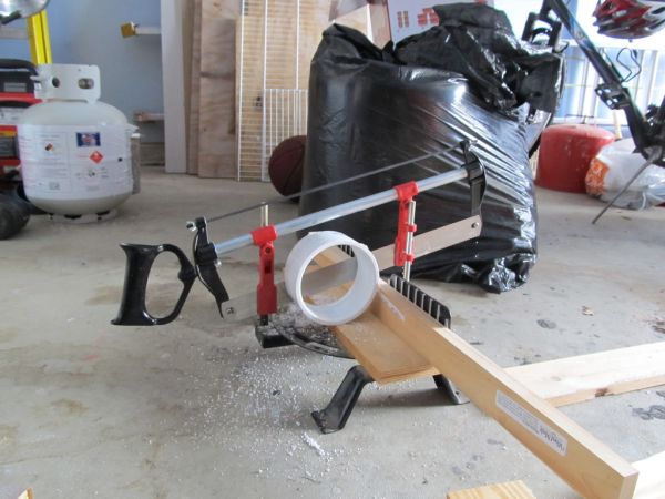
Step 2: Cutting and Drilling
We are writing these instructions the same way we made the SODAR but this is a reminder that we only ended up needing 3 PVC pieces.
PVC editing:
Using a miter box, saw the PVC so that all 4 PVC pieces are the same height. In our scenario, that would be approximately 1 & 3/8″ in. Afterwards, level the PVC bases with coarse grain sand paper so that it would be flush against the tile.
Tile editing:
Cut a 6″ x 6″ piece off to use as a base for the PVC. From the center of the piece, mark the outer edges of the 4 PVC pieces with a compass. Then drill a central hole atleast 5/16″ and three holes for the wires at 1/16″ (one hole per section).
Step 3: Gluing: PVC to Base & Balsa to Styrofoam
Secure the PVC
With the goop, glue wires with stripped ends into the 1/16″ holes that were drilled into the tile. Glue these so that about an inch of exposed copper is above the tile and at least a foot of sheathed wire protrude below. Afterwards, apply an even, thick layer of Household Goop on the bottom of the PVC pieces and secure them to the 6″ x 6″ tile. Use the outlines drawn in the previous step for proper placement. Make sure that each wire is only in its own section (to prevent shorts in the circuit) and that there are no gaps in the glue that liquids could pass through (and short the circuit). Let the goop dry as described in the instructions.
Secure the styrofoam
Find the center of the styrofoam with a ruler and poke a hole through the middle with a pin. This pin will act as a guide for centering the coupler. In our scenario, we dug through our pens searching for a pen body that fit somewhat snugly to the stepper motor shaft. Once the coupler is centered on the styrofoam, secure 4 6″ pieces of 3/8″ x 3/8″ balsa wood around the coupler with Gorilla Glue. Do not glue the coupler into the center yet. The balsa wood design is shown in the picture.
Note: You may want to clamp the balsa wood down or put something flat and heavy on top of it to prevent the Gorilla Glue from expanding in such a way that the balsa wood is not level. Also, since you will be putting the coupler into the center of this later, be careful not to use too much Gorilla Glue or risk filling the center piece when it expands.
Warning: There are a good amount of strong adhesives out there that will eat through styrofoam (think napalm-like reaction). We first tried adhesion with the household goop and, needless to say, we had to go buy a new 6″ styrofoam piece.
Step 4: Test for Water-Tight Seal
Fill the sections with water, looking for any leaks. If you want to, you can fill all three and then put a drop of food coloring in each looking for cross bleeding. In our scenario, we did this step after Step 5, but a leak would be much less damaging if found before that step so we recommend doing the test at this point.
Step 5: Add Lower Platform
With the upper platform flipped so the tile is on top, place the stepper motor shaft into the center hole. Cut eight 3″ long 3/4″ diameter dowel pieces as spacers between the upper and lower platforms. Using Goop, glue four of the pieces so that the motor is stabilized. Glue the other four farther away from the center so that the weight is more evenly displaced. Glue a second 6″ x 6″ piece of the tile to the bottom of this and let it dry. It is best to have the motor securely flat against the bottom tile. However, if you don’t want glue on the motor (like us), and lift it, you run the risk of having to put small spacers to level is after everything dries (like us). The picture shows the piece after this step with the uncut coupler (a pen with fun tack).
Note: An alternative to this step would be to not have the innermost PVC piece (since only three are needed), and instead have the motor up, level with the PVC on the initial tile base.
Step 6: Binding Bottom to Top
Cut the coupler:
Measure the length of coupler (pen) that you want to use, including a gap between the PVC and balsa wood. In our project, the gap was 1/2″.
Binding the pieces:
Add Gorilla Glue to the center of the styrofoam, between the 4 balsa wood pieces. Place the styrofoam upside down so the balsa wood is facing up and put spacers between the balsa wood and PVC (we used 3″ x 1/2″ x 1/2″ balsa wood pieces). After securing the coupler to the stepper motor shaft, place it on top of the styrofoam. The weight of this piece will prevent the expansion of the Gorilla Glue from tilting the styrofoam relative to the coupler.
Step 7: Downloading Code
Arduino, Processing, and Our Code
To control the SODAR device, the Arduino must be correctly programmed, and the computer must communicate with it through the serial port. We have writtenArduino code and Processing code to do just that, and it’s all available at our GitHub repository.
Stepper library
In order to get the required angular functionality from the stepper motor, we have made some custom additions to the Arduino stepper library. The updated library supports all of the same functions as the default stepper library. It is included in the libraries/Stepper directory in our repository. Just find the libraries/Stepper directory that Arduino uses and replace it with the new one.
NewPing library
For smooth operation, we also implemented interrupt-based PING sensor code using the NewPing library, available for download here. Download this and place it in the libraries directory of your Arduino sketchbook.
Note: The Arduino code must be uploaded to the board before running the Processing UI because the UI takes control of the serial port.
For mor detail: DIY 360 Degree SODAR Device