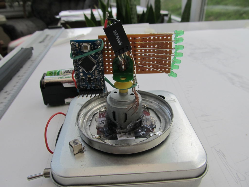
A zoetrope is a mechanical device that animates a series of pictures by spinning them fast enough that the images appear to merge together and move, My digital zoetrope works on a similar principal, by flashing the LEDs while they are spinning it is possible to display text, patterns and possible even simple animations. My design uses an Arduino Pro mini powered by a system of brushes and a magnet and hall effect sensor for position detection.
Step 1: Materials
I used an Arduino Pro Mini from Sparkfun as the projects controller, the motor is just a small hobby motor which can be bought cheaply or salvaged for free. You’ll need 7 LEDs and resistors for them, use resistor values slightly lower than those specified for your LED type, the LEDs will be switching on and off very quickly so they’re not at as much risk of being damaged by the current, The resistors I used where too high so the LEDs arn’t as bright as they normally would be when it is spinning.
The Hall Effect sensor was bought several years ago so I’m missing its actual parts number but it has an analog output on its middle pin that gives a reading that is proportional to the magnetic field strength on the sensor. I also used a small neodymium magnet to trigger the sensor.
I used two tins to create the base of the zoetrope, the square tin just acts like a case but the round tin lid on top must be conductive as it will be the Arduinos negative supply..
Step 2: Electronic circuitry
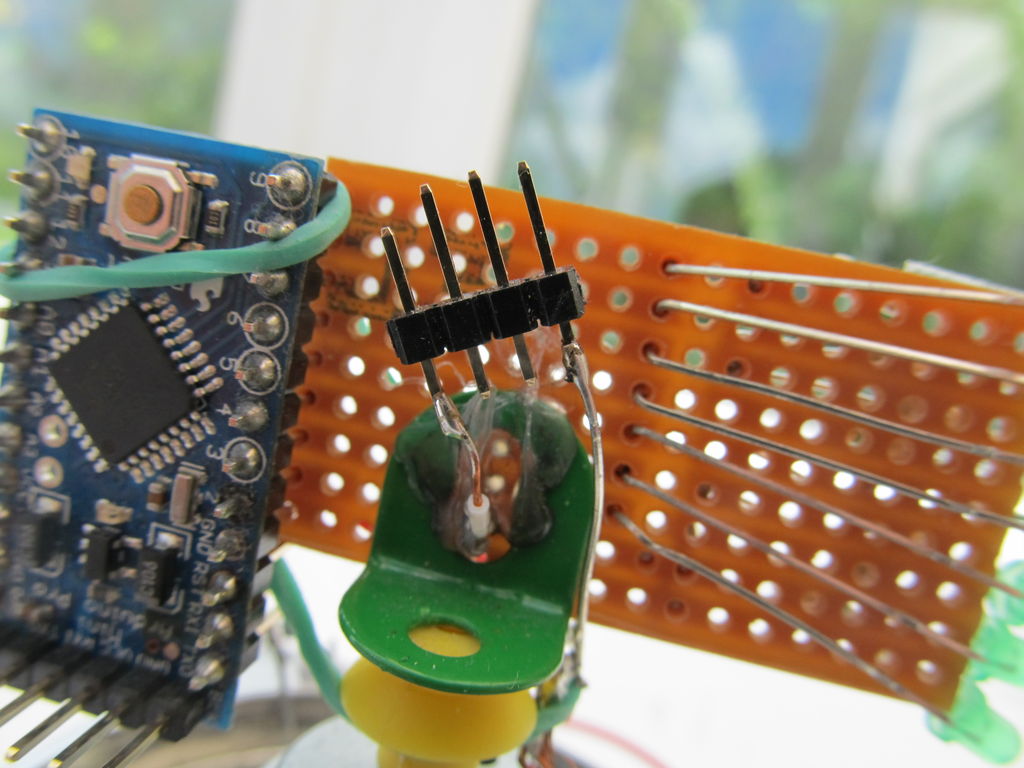
The 7 LEDs are soldered to a piece of stripboard, with their positive leads connected together each with an individual resistor, I connected the negative LED leads to pins 3 to 9 on the arduino pro mini, see the 2nd picture to see how I wired it up in more detail.
I power the circuit through 4 AA batteries which give an output of 6v theoretically but in reality it is slightly less, although it is sufficient to power the Arduino and motor. A battery clip is connected to the motor via a switch, the negative lead is soldered to the lid of the tin for the brush to connect the Arduino to ground. The positive lead comes from the switch to one input of the motor and I soldered a small piece of wire from the positive motor input to the motors metal housing.
Step 3: Arduino power brushes
To power the Arduino while it is spinning there are two brushes, The barrell of the motor is connected to the positive lead to the battery, I used a piece of copper wire to act as a brush to make a contact while the device is spinning, thew other end connects to the stripboard which is connected to the positive LED legs and the Arduino VCC pin.. I used an elastic band wrapped around the Arduino body and hooked onto the brush to hold the brush to the motor casing tight.
In the last step I showed how the negative lead from the battery connector is connected to the lid of the tin. To make the negative brush I used a dremel to cut the middle out of a circular tin lid, after using a multimeter to check its conductivity, I then soldered the circular tin lid to the top of the square tin lid and used a piece of bent paperclip soldered to a GND pin and bent into shape so the curved end fits in the rim made by the tin lid.
Step 4: Construction
The construction of the device is pretty straight forward, I used a dremel to cut a hole through the square tins lid which I hot glued the motor into, make sure the glue goes all the way around and be careful that the metal of the tin lid doesn’t touch the motor casing or it will short circuit.The magnet is strong enough
To attach the stipbooard to the pulley on the motor I used a Mechano bracket and superglue, to prevent as much vibration as possible I bent a piece of wire to a right angle, I then used this piece of wire to find the centre of gravitiy of the stripboard by hanging the board through the holes until it balanced. I then put this centre of balance over the motors axle as close as i could by eye.
For more detail: Digital Zoetrope using Arduino