RGB LEDs are fairly useful in projects allowing for a wide range of color from a single unit. However they can be a pain in the neck to work with and they too often come with little or no documentation. I searched for some time to find a common resource on them and this Instructable is an attempt to pool the fruits of that search into one place.
But first, a word about diodes. What is a diode? It is the electronic equivalent of a one-way valve. They have a flow direction, and if inserted backwards do not work. They prevent the voltage from flowing through, except in the direction of their flow. The first diodes were used as rectifiers in decoding radio signal modulation. For more on the history of the Diode, your welcome to check them out on Wikipedia http://en.wikipedia.org/wiki/Diode
Whats that have to do with LEDs you ask? Well LEDs are by nature diodes. It is in their name — Light Emitting Diode. This means that if you cross connect the Anode (+) and the Cathode (-), nothing happens and your circuit fails. Usually resulting in nothing more than an open circuit as voltage cannot flow. For more on the history of the Light Emitting Diode, or LED, you can go here on Wikipedia http://en.wikipedia.org/wiki/Light_emitting_diode
Four pin RGD LEDs are a little different. They share a common Anode, but three separate Cathodes, one for Red, one for Green, and one for Blue. If your not careful you can pass current through conflicting parts and cause a spectacular failure complete with a snap, a pop, a whiff of ozone, and plastic shrapnel flying all over your workspace.
This is usually caused by the omission of a current limiting resistor to the circuit (yes, I’m guilt of this). Incidentally, this sort of failure is not covered by Radio Shack’s warranty.
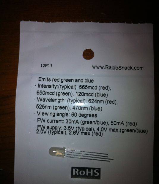
The LED in this project was purchased at a local Radio Shack and has the following part number, 276-0028
Step 1: The Pinout
One of the most annoying part of these little gems is the lack of a pinout diagram that was useful.
While looking at the photo, you will notice that the four pins are three different lengths. Also there is a flat side of the housing on the left side. With the flat side to the left, as in the photo, the pins are: RED Cathode (medium length pin), Common Anode (longest pin), , BLUE Cathode (shortest length pin on the inside), and GREEN Cathode (shortest length pin on the outside). This is not how I would have designed the unit as I think it would be easier to keep up with it if were Red-Green-Blue, but that’s logic for you.
A quick look at the datasheet screen-printed on the package indicates that the different Cathodes use different current levels. 2.0V to 2.6V max at 50ma for the Red, and 3.5V to 4.0V at 30ma for the Green and Blue. Its important to note this when calculating what resistor(s) are necessary for your project.
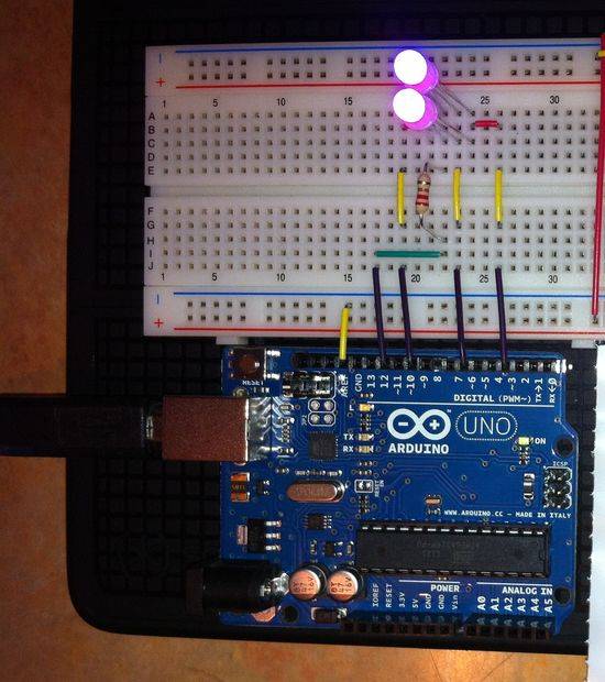
Step 2: Placement on a Breadboard
With four pins close together you need to make sure to place each pin in a different column on your breadboard. This will require slightly bending the legs to accomplish. You might want to use a precision screwdriver or toothpick or similar object to assist you in placeing the pins in the desired socket.
If your hooves are as large as mine, you may find it useful to use lateral jumpers to open up the area your working with.
For more detail: Demystifying 4 pin RGB LEDS (Radio Shack 276-0028)