n this project, we will go over how to integrate a keyboard with an arduino board so that the arduino can read the keys being pressed by a user.
Keypads are used in all types of devices, including cell phones, fax machines, microwaves, ovens, door locks, etc. They’re practically everywhere. Tons of electronic devices use them for user input.
So knowing how to connect a keypad to a microcontroller such as an arduino is very valuable for building many different types of commercial products.
At the end when all is connected properly and programmed, when a key is pressed, it show up at the Serial Monitor on your computer. Whenever you press a key, it shows up on the Serial Monitor. Later, in another project, we will connect the keypad circuit, so that it will get displayed on an LCD. But for now, for simplicity purposes, we start at simply showing the key pressed on the computer.
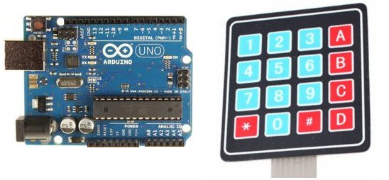
For this project, the type of keypad we will use is a matrix keypad. This is a keypad that follows an encoding scheme that allows it to have much less output pins than there are keys. For example, the matrix keypad we are using has 16 keys (0-9, A-D, *, #), yet only 8 output pins. With a linear keypad, there would have to be 17 output pins (one for each key and a ground pin) in order to work. The matrix encoding scheme allows for less output pins and thus much less connections that have to made for the keypad to work. In this way, they are more efficient than linear keypads, being that they have less wiring.
Components Needed
- Arduino
- 4×4 Matrix Keypad
- 8 male to male pin header
The 4×4 matrix keypad can be obtained from a number of retailers online. It can be purchased at amazon and many other online retailers if you google the part.
The type we will use is by an electronic manufactuer called Sunkee.
One of the most mysterious things about these keypads is that they usually come with no documentation, so a user is left to figure out the pin configuration for him or herself. However, we at this site, have figured it out.
With the keypad facing up so that the keys are up and facing you, from left to right, the 1st 4 pins are the row pins and the last 4 pins are the column pins.
When connecting the pins to the arduino board, we connect them to the digital output pins, D9-D2. We connect the first pin of the keypad to D9, the second pin to D8, the third pin to D7, the fourth pin to D6, the fifth pin to D5, the sixth pin to D4, the seventh pin to D3, and the eighth pin to D2.
These are the connections in a table:
| Keypad Pin | Connects to Arduino Pin… |
| 1 | D9 |
| 2 | D8 |
| 3 | D7 |
| 4 | D6 |
| 5 | D5 |
| 6 | D4 |
| 7 | D3 |
| 8 | D2 |
Keypad with Arduino Circuit Schematic
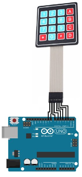
This is a visual of how the circuit is when connected up.
For more detail: How to Connect and Read a Keypad with an Arduino