Design:
The rotational motion produced by the motor is transformed into linear motion through the use of a standard 1/2″-13 threaded rod as a lead screw. To account for angular misalignments in the rod the motor is not attached to it directly, but rather through a belt and pulley system. The ball bearing screen door roller is added to increase the tension and to combat the stretching in the belt. In order to prevent the block from moving too far to the left or right two pin plunger switches are emplaced at the desired limits of motion. When the block depresses one of the plungers the microcontroller switches the rotational direction of the motor.
The laser has a removable lens cap which allows the laser to produce a vertical line, rather than just a narrow beam. This solves one of the major problems encountered in the early design process. Because the system can only find horizontal position the phototransistor would have to be at the same vertical height of the laser if it was only producing a narrow beam, otherwise, the laser would just pass above or below the sensor. The fact that the laser creates a line instead, however, means that the vertical position of the phototransistor is no longer important.
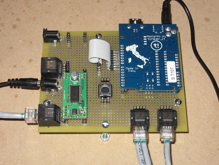
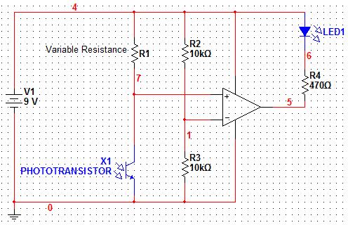
Another problem encountered during construction was the necessity to take into account varying ambient light conditions. The light in one room, or even section of a room, will be different from another and if it is too bright the phototransistor will incorrectly activate. The phototransistor’s sensitivity is determined by a particular resistance in the circuit, R1 in the diagram below. To solve the problem this resistance was made to be adjustable. There are three pairs of headers in which three resistors can be connected in series. Increasing the resistance increases the sensitivity, and vice versa. If fine tuning is desired, an appropriate potentiometer can be added instead of a standard resistor.
Rather than using the provided microcontroller board, an Arduino Duemilanove card was chosen to control the system. The other component on the circuit board is an EasyDriver v3 stepper motor driver. This part allows the motor to be controlled though the use of only 2 digital output pins as well as simplifies the code. RJ45 jacks allow for communication and power transfer between the motor, the sensors, and the microcontroller using standard Ethernet cables.
For more detail: Computer Controlled Aiming Method