The wife is into raising chickens and now that the daylight savings is getting near she wanted a way to keep the egg laying production in high gear. According to the material that she reads, chickens will maintain their egg laying production if they get 12 – 15 hours of daylight.
I thought to myself, what a great opportunity for me to put together a DIY electronics project that would also be green. I wanted a quick and inexpensive solution so I decided to go with the Arduino as the MCU and build everything from scratch.
This document will document my project from beginning to end.
I had picked up a battery powered LED light that would be great for this project.
I have a bunch of ATMega chips lying around as well as a few Arduino clone boards, so I was well on to my way of building this project with material and parts that are in my parts bins in my shop.
I started to think about what kind of design I wanted and decided to go simple, lean and mean.
I have done some work with latching relays in the past and really like the idea of using the MCU to latch the relay on and off without having to keep constant power on the ATMega ports all of the time.
The chicken coop is located in an area where there is no easy access to AC power and I wanted a battery solution that I could, at a later date, add solar panel access for charging.
First off I had to determine the volts and amp requirements of the LED light.
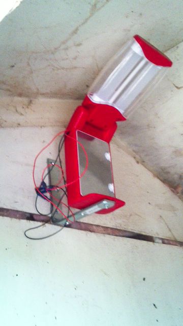
I took the LED light apart and soldered some wires to the existing switch circuit so I could trigger the light with the relay.
The LED light consumed 6 volts at around 500 milliamps.
D-cell batteries originally powered the LED light. I did not want two different battery sources and I did not want to change batteries all of the time. So I decided on a single battery source to power the MCU and LED light.
Below is image of LED light mounted in Chicken coop, two wires for switch and two wires for power:
Step 1: Breadboard
Once I decided on a circuit I laid out the circuit on a breadboard using an Arduino clone as the microcontroller. This way I could test the circuit using components that I knew worked and gave me a stable platform to write the code.
I also do not like to power external devices directly from the microcontroller ports so I decided to use some NPN transistors as part of the relay circuit.
To provide an accurate time source for the relay timer I decided to use a DS1307 RTC, Real Time Clock chip. LadyAda has a really good write up on using this chip and has created her own code branch of JeeLab’s RTCLib library.
Here are the links to the web sites:
http://www.ladyada.net/learn/breakoutplus/ds1307rtc.html
https://github.com/adafruit/RTClib
The breadboard shows a SparkFun DS1307 RTC, I have several of these that I use for testing purposes.
But the production version of the Light Relay board uses the same RTC board that LadyAda documents in her writeup.
The Arduino clone pictured is the Diavolino from Evil Mad Science Labs. Nice board and very inexpensive. I use this board as one of my prototype boards.
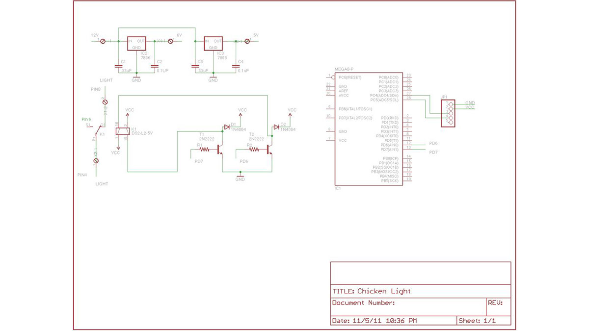
Since I needed two different voltages for this configuration, 5 volts for the microcontroller and 6 volts for the LED light, I decided to use two linear power regulators. For low cost I decided to use 7805 and 7806 regulators to drive the microcontroller and the LED light.
Since I wanted to keep the price low, I decided to build the production version of the circuit board on solder based breadboards.
After building this board, I learned a lot of lessons, In the future, I more than likely take the time to build my own custom PCB boards.
Building the solder breadboard was very time consuming and tedious.
Step 2: Production Breadboard
Here is a shot of the finished production breadboard:
Notice the terminal blocks on the breadboard.
The left terminal block is connected to the two switch wires of the LED Light. The output from the relay is connected to this terminal block.
[box color=”#985D00″ bg=”#FFF8CB” font=”verdana” fontsize=”14 ” radius=”20 ” border=”#985D12″ float=”right” head=”Major Components in Project” headbg=”#FFEB70″ headcolor=”#985D00″]Arduino
Led
Breadboard[/box]
For more detail: Chicken Light Timer using an Arduino