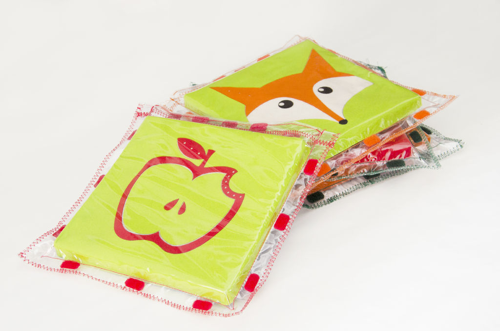
This tutorial will show you how to build an interactive toy for children. This toy wants to give a boost to children to move and play with friends at home or in a park, instead of watching TV and playing videogames.
Catchin’ time is a project developed during our thesis in Ecodesign at the Polytechnic of Turin. This modular toy can be used for jumping (when you connect the elements together to create a carpet) or for running (if you wear it on your back, e.g. Tag or other traditional children’s games).
How does it work? Each element has white LEDs, a little buzzer to generate a sound and a capacitive sensor made of conductive fabric. When children jump on it or hit it with hands to turn off LEDs, buzzer rings and a wireless signal is transmitted which activates LEDs on another element!
Playing at home The carpet is made by the union of several modules where the child can jump responding to a light pulse. Our tutorial allows the creation of two modules: ModuleA, used to send data and ModuleB, used to receive data.
Playing outside Single modules can be worn by children and allow them to play traditional games in a technological way. When the child is picked up by his friends, the module on his back beeps and LEDs turn off, until he is touched again by a teammate.
It is possible to create many different games starting from our modules, you have only to make the toy, use your imagination and create new sketches!
Do you prefer Italian instructions? Follow us on Facebook 🙂
Step 1: SUPPLIES
To realize each element you need:
Electronics
– 1 Lilypad USB Atmega32U4 Board (Sparkfun Electronics – Robot Italy)
– 1 micro USB connector (NB. You can use your smartphone’s cable)
– 1 Lilypad Xbee Shield (Sparkfun Electronics – Robot Italy)
– 1 Xbee 1mW Trace Antenna Series 1 (802.15.4) (Sparkfun Electronics – Robot Italy)
– 1 serial USB UART converter (like this FuturaShop)
– 5 Female Header pins (Sparkfun Electronics – Robot Italy)
– 1 mini USB connector (NB. You can use your camera’s cable)
– 10 white Lilypad LEDs (Sparkfun Electronics – Robot Italy)
– 1 Polymer Lithium Ion Battery 3.7V (1000mAh Sparkfun Electronics – 1400mAh Robot Italy)
– 1 Lipo Charger Basic – mini USB
– 1 Conductive Fabric – 30×33 cm Ripstop (Sparkfun Electronics – Robot Italy)
– 1 Conductive Thread Bobbin – 10 m (Stainless Steel) (Sparkfun Electronics – Robot Italy)
– Copper wires
– 1 resistor 220 ohm
– 1 resistor 2.2 Mohm
– 16 mm Speaker (Robot Italy)
Materials (you can use materials and tools you have at home, or you can buy them in a DIY store)
– 2 or 4 felt pieces – 23×23 cm (colours and numbers of pieces depend on chosen pattern)
– 2 strips of Anti-slip pad – 4x18cm
– Velcro
– Grey shock adsorber pad – 20x20x1cm
– Blue shock adsorber pad – 20x20x0,3cm
– 2 small plastic cups to protect electronics
– Thermal paper for iron – 23×23 cm
– 2 pieces of canvas – 20x20cm
– PVC clear wrap – 25x56cm
– 2 kid singlets or waistcoats
Tools
– Scissors and cutter
– Leather Hole Punch (for belts)
– Pyrograph
– Soldering iron
– Fabric and plastic glue
– Sewing kit
– Iron
– Sewing machine
– Alligator clips
– Electrical tape
Step 2: PREPARE THE MODULE
– Take a paper sheet and cut out the mask of the grey pad of the module (link Mask)
– Use the mask to cut the grey pad with a cutter.
– Take two rigid plastic boxes (we used the packaging of chewing gum but it would be better to use a more rigid shell). Cut the boxes as tall as the thickness of the grey pad, these boxes will be used as cover for electronics. The circular cuts in the grey pad could have different diameters, depending on the chosen coverage.
– Engrave the grey pad with a pyrograph to obtain the necessary space for the 16mm speaker.
– Select the desired felt pattern (link fairy tale pattern – link pets patterns), draw it on a piece of felt (23×23 cm) and cut it out. Pierce the felt in the position you want to insert the LEDs with a belt punch. Mark this holes on a 20x20cm canvas, in this way you know where to sew the LEDs.
– Compose the pattern on the reverse side, lay down the thermal paper (the shiny side of the paper facing the felt), cover it with a sheet of baking paper (to prevent the fabric from sticking to the iron) and do the ironing.
– When the felt is cooled, you have to sew the corners of the felt in order to create a cover for the module (that measures 20x20x1,5cm).
– Take the PVC clear wrap, cut it in 2 parts in order to obtain 2 rectangles 25x28cm, fold one end of the long side of 2cm and sew it with a zigzag, to obtain a resistant board. Reinforce also the other rectangle, join the two sheets sewing them with straight stitching on the three free sides and finish with a zigzag on the same sides. The obtained case should be able to contain 20x20cm module.
– Turn the obtained package on the back and glue two strips of anti slip pad (4x18cm) and two strips of Velcro (to hang the module on the back of the child).
NB. Use a glue suitable for plastics
– In order to join the modules together, you have to cut out 8 Velcro rectangles 2x1cm: then paste 6 of them along the perimeter of the envelope and the remaining 2 inside the reinforced edge (to close the module).
(link Velcro).
NB. Use a glue suitable for plastics
Take 2 singlets (or 2 waistcoats) you have at home, and glue 2 strips of Velcro on the back, so that children can hang the modules.
Step 3: PREPARE ELECTRONICS
LED
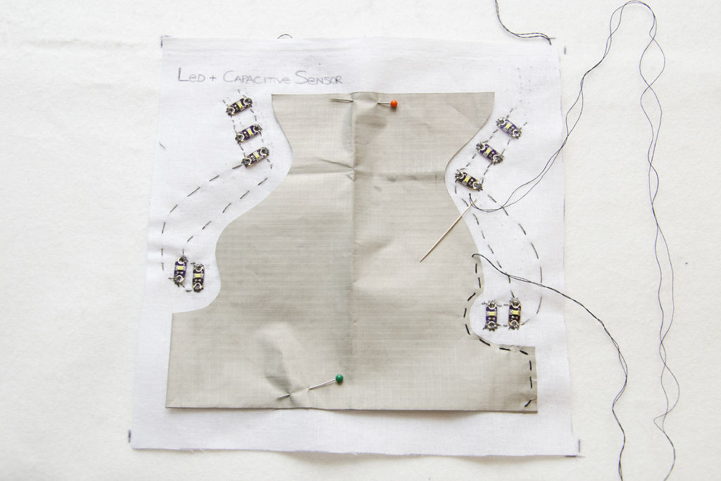
– Take the canvas with the positions of LEDs, fix them with the glue and sew them in series with conductive thread; you have to leave a long thread at the end of the seam. Check with the Blink sketch (basic example of Arduino sketches) if LEDs are properly connected.
Capacitive Sensor
– Take the conductive fabric, cut it out so that it doesn’t touch the threads of LEDs and sew its hems on the canvas with NO conductive thread. Sew the centre of the conductive fabric with the conductive thread to allow the passage of the electricity.
For more detail: Catchin’ time using Arduino


