Capacitors are vital components in electronics, but sometimes they are broken, or the value printed on the cap has become unreadable. Because my multi-meter does not have a capacitance measurement, I decided to make one!
The principle of measuring capacitance is quite simple. The voltage of a capacitor charging through a resistor increases with time T. The time it takes to reach a certain voltage, is related to the values of the resistor and capacitor. In this project, we’ll use a 555 timer circuit as a monostable multivibrator. If that sounds like some dark magic to you, don’t worry, it’s quite straightforward. I’ll refer to the the Wikipedia page for the details, as we’ll focus on the things we really need: the schematic and formula. The time in which the capacitor C charges through the resistor R is given by: T = ln(3) x R x C = 1.1 RC. If we know the value of the resistor and the time, we can calculate the capacitance: C = T / 1.1R.
Now we need a device for measuring the time, and that is where the Arduino comes in. The time is defined by the state of the output pin of the 555 timer (pin 3). It will be HIGH when the capacitor is charging, and LOW when it’s not. This means the output generates a pulse with length T.
The Arduino will be connected to pin 3 and will be detecting the rising and falling edge (transition form 5V to 0V and vice-versa). By using the function micros(), we’ll know how long the pulse is, and we’ll calculate the resistance.
The value of the resistor can be chosen freely. We’ll take 1 MOhm for measuring low capacitance (nF range), and 10kOhm for higher capacitance (uF range). Otherwise, measurements in the uF range would take ages.
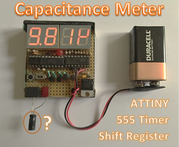
Finally, the value of the capacitor should be displayed on a screen; I chose a 4-digit 7 segment display. Those displays need a lot of inputs, so we’ll multiplex them to resolve this issue. Basically: we’ll drive the displays one by one, but so fast that the human eye cannot notice. We’ll also use a shift register to further decrease the number of Arduino pins we need. The shift register will read the data from the Arduino over 2 wires, and then drive the display through 8 wires. This is well explained here: http://www.instructables.com/id/Multiplexing-with-Arduino-and-the-74HC595/ .
For More Details: Capacitance Meter