In this project, we are going to build an RGB Full Color LED module circuit.
A full color LED module is a circuit in which an LED can be lit to any color. This is why it is called a full color LED module. By programming the module with a microcontroller, we can program the LED to turn to any color that we want.
How the module works is it has 3 PWM (pulse width modulation) pins which stand for the colors red, green, and blue (RGB). The idea is that any color can be created with a combination of red, green, and blue.
By blending red, green, and blue, we can showcase all colors (full color) with the LED on the module board.
The RGB full color module is actually a very useful circuit. Using a single LED, we can lit up any color that we want. We can show orange, green, red, anything. It’s really good if you want a wide variety of colors and you only want to use a single LED.
In this circuit, we will build a circuit in which all the possible colors are showcased. We will show a blend of all the colors which the LED can show in rapid succession with a for loop.
Components
- RGB Full Color LED module
- Arduino
The RGB full color LED module can be obtained cheaply on ebay.
It is a 3-color full color LED module.
It works on 5V of power, which is perfect with the arduino, because this is what the arduino digital pins provide. When the digital pins are held HIGH, then the pin gets 5V and LED turns on.
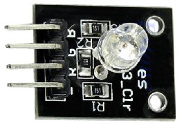
Onboard you will see that there are 3 150Ω resistors. Even though there’s only one single LED, there are three separate pathways that power can go to the LED. These pathways are the red, green, and blue digital pins. Therefore, there’s a need a separate resistor for each pathway. These resistors function as current-limiting resistors, so that the LED doesn’t g get burned out by excess current. So you don’t not need to add any current-limiting resistors to this circuit. They’re already on the board.
So the digital pins are how the circuit board gets its positive voltage. The only thing else we need to do is connect the – or ground pin to GND on the arduino board. This gives power to the board.
The module has 4 pins, R, G, B, and -.
R stands for the red color.
G stands for the green color.
B stands for the blue color.
– completes the ground connection, so it gets connected to ground.
The pin connections are very simple.
RGB Full Color LED Module Circuit
The full color LED module circuit we will build to showcase all the colors that the LED can is shown below.
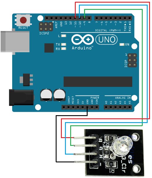
The connections are very simple.
Each of the RGB PWM pins get connected to a digital pin on the arduino board.
The Red pin gets connected to digital pin 11.
The Green Pin gets connected to digital pin 9.
The Blue pin gets connected to digital pin 10.
And the – pin gets connected to ground.
Next all we need is the code.
Code
This is the code necessary for the RGB full color module to showcase all its colors.
int RedPin = 11; //the Red pin connects to digital pin 11 on the arduino
int BluePin = 10; //the Blue pin connects to digital pin 10 on the arduino
int GreenPin = 9 ;//the Green pin connects to digital pin 11 on the arduino
int value; //this will hold the value of a for loop we will create
void setup() { pinMode(RedPin, OUTPUT);
pinMode(BluePin, OUTPUT);
pinMode(GreenPin, OUTPUT);
Serial.begin (9600);
}
void loop()
{
for (value = 255; value>0; value–){//counts down
analogWrite(11, value); //val will be 255 initially
analogWrite(10, 255-value); //val will be initially 0 initially
analogWrite(9, 128-value //val will be initially 127
delay(1);
}
for (value = 0; value <255; value++)//counts up
{ analogWrite(11, value);//val will be 0 initially
analogWrite(10, 255-value);//val will be 255 initially
analogWrite(9, 128-value);//val will be 255 initially
delay (1);
}
Serial.println(value, DEC);
}
This code will show the full spectrum of colors.
The first block of code shows the pin connections to the arduino board and creates an integer named value.
The second block of code, the setup() function, makes all the digital pins (R, G, and B) output pins. Serial.begin(9600) allows us to open up a Serial Monitor so that we can see the value that the for loop is currently running.
The next block of code, the loop() function is run repeatedly over and over again. It contains 2 for loops. The first for loop counts down from 255. The second for loop counts up from 0. Between each new value is a 1ms delay. If you want you can change this delay to faster or slower to suit your preferences. If you want to see it go slower, then you increase the delay. If you want to see it go even faster, which you probably wouldn’t want since it’s going fast already, you can use DelayMicroseconds() function to make it faster.
This circuit creates really cool lighting effects.
But probably the best use for it is that it can show any color once you know the correct values. .
For more detail: How to Build an RGB Full Color LED Module Circuit