You’ve started modifying sketches, and played a bit with the onboard LED (or if you have an NG, an LED you added). The next step is to start adding onto the hardware component of the Arduino. We will do this by adding a solderless breadboard to our setup, connecting up new parts with wire.
Solderless breadboards are an important tool in your quest for electronics mastery. They allow you to make quick circuits, test out ideas before making a more permanent Printed Circuit Board. They’re also inexpensive and reusable.. You can pick on up at any hobby shop or electronics supply store. They often look like this
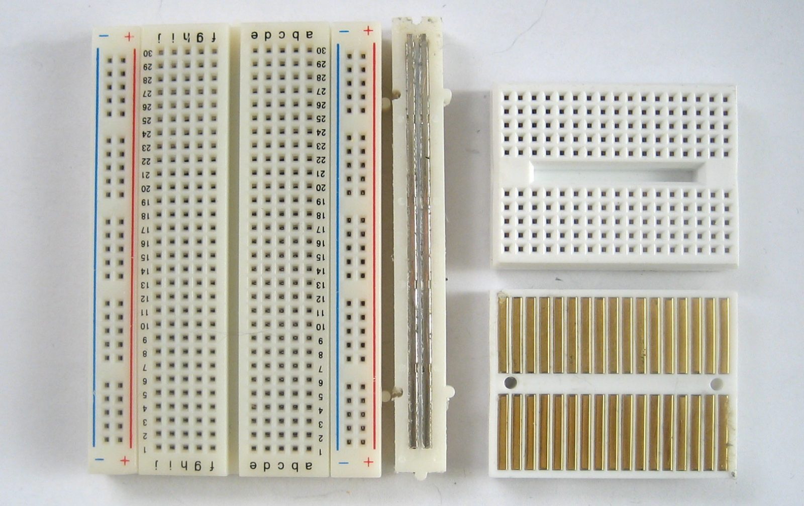
Basically, a chunk of plastic with a bunch of holes. However, something special is going on inside the breadboard! Although you can’t see it, inside the breadboard are many strips of metal that connect the rows and columns together. The metal strips are springy so that when you poke a wire into the hole, the clips grab onto it.
In the images above you can see how there are two kinds of metal strips. There are short ones that connect 5 row holes at a time, and then there are very long ones that connect 25 (or more!) column holes at a time. The long columns are called rails and the short strips are called rows. Breadboards are almost always made so that they have two sets of 5-hole rows and on either side there are a pair of rails. For example the breadboard on the left has 30 row pairs and 2 sets of double rails on either side. The one on the right is quite small, it has only 17 row pairs and no rails.
In this lesson, we will show pictures of both the tiny breadboard on a protoshield and also using a ‘standard’ breadboard without a shield. However, after this lesson, you’ll be more on your own to figure out how to connect up the standard breadboard, OK?
Warning!
Distressing as it may sound, solderless breadboards can be very flakey, especially as they age. If you’re having problems with your circuit, it could be that the little metal clips on the inside aren’t working well. Try poking it with your finger, or moving it to a different section.
To use the breadboard, you’ll need jumper wires. These are basically 22 gauge solid-core (not stranded) wires that are cut down and have the insulation pulled off. You can use a fingernail or, best of all, a real wirestripper tool to remove the insulation, just takes a few tries and then its really easy.
Heres how to do it with just diagonal cutters…Cut the wire first, using wire cutters
Nick the insulation, then pull it off.
To connect rows together, just stick the wire ends without insulation into the square holes!
Now is a good time to practice making jumpers, go forth and make a few 3″ long jumpers!
The resistor is the most basic and also most common electronic part. An electronic gadget, such as an mp3 player has easily a thousand resistors inside of it!
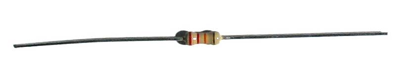
Behold…a resistor!
Resistors have one job to do, and that is to resist the flow of electricity (otherwise known as current). That’s why they’re called resistors. By resisting current they control where and how fast it flows.
One common way of thinking about this is if we were talking about water current, then pipes are like resistors. Thin pipes let less water through (high resistance), thick pipes let a lot of water through (low resistance). Wth a fire hydrant, you want low resistance. With a water fountain, you’d want high resistance. If you mixed up the two pipe sizes, you wouldnt be able to put out a fire and you’d hurt yourself while trying to get a drink.
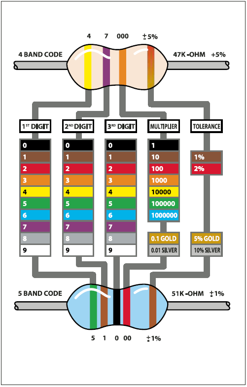
Resistance is measured in ohms, often written as the symbol Ω. The bigger the resistance value (in ohms) the more it fights. Most resistors you’ll see range between 1 ohm and 1 megaohm (1.0 MΩ). Since the resistive element is inside a ceramic casing, its not possible to tell the resistance of a resistor just by looking at it. You’ll have to read it by looking at the colored stripes on the body of the resistor. This is known as the resistor color code, and its a real pain when you first start electronics. Eventually you’ll get really good at telling the value of a resistor just by glance but to start off you’ll want to use a reference chart. (Or you can use a multimeter to measure the resistance accurately)
Click here to view a reference chart that you can print out (in color) and use as your guide.
There are also website calculators that you may find very handy
Remember: Just because the stripes are in a certain order doesn’t mean the resistor has a direction! Resistors are the same forward and backwards, it doesnt matter which way they are used.
Quick quiz!
- What is the color code for a 5% 1.0KΩ resistor?
Highlight the text below to see the answer
Brown – Black – Red – Gold - What is the color code for a 5% 220Ω resistor?
Highlight the text below to see the answer
Red – Red – Brown – Gold - What is the value of this resistor?


Highlight the text below to see the answer
The stripes are yellow (4) – violet (7) – red (* 100) = 4700 Ω = 4.7KΩ - What happens if you put a resistor in backwards?
Highlight the text below to see the answer
Ha! Trick question, it is not possible to put a resistor in ‘backwards’. They work either way!


Note on Wattages….
In all these examples, we use 1/4W resistors. Unless otherwise noted you can use 1/16 W or 1/2W or whatever you can get your hands on. Higher wattage resistors are larger and usually more expensive, but sometimes your local hobby shop will only have 1/2W.
We’ve had some time with the LED already, but lets get to know her a little better. The word LED stands for Light Emitting Diode. The light-emitting part, well, that makes sense. We’ve used the LED to make a blinking light in lessons 1 and 2. The LED component turns current into light, much like any sort of light bulb. But what is this mysterious diode?
A diode is basically a one-way street for current. Imagine such a one-way street with a traffic policeman in front. If you want to turn onto the street the wrong way, he will not let you. Likewise the diode simply does not let current go through it the wrong way. Current in a diode can only flow from the positive side to thenegative side.
If you recall from lesson 1, Arduino NG users had to make sure that they inserted the LED in the right way. If you place the LED in backwards it won’t work. Diecimila Arduino users already have the LED (a very very small one) soldered onto the circuit board the right way.
Look again! Its a tiny LED
As we mentioned before, its easy to figure out which side of an LED is positive and which one is negative. The positive leg is slightly longer and if you look inside, the chunk of metal is larger on the negaive side.
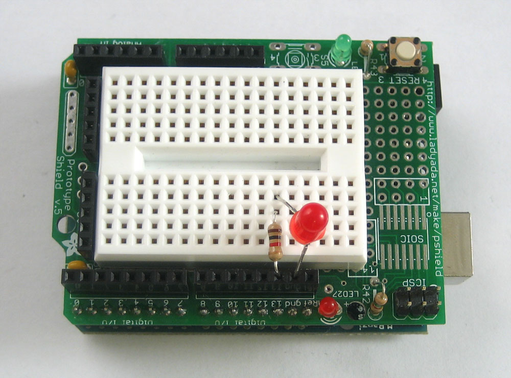
We’re going to now use the breadboard to light up an LED. You will need a breadboard, an LED and a 1.0K ohm resistor (brown black red gold). If you have a protoshield, make sure its assembled first. Then, place the tiny breadboard on top. You can remove the backing to stick it on (which is permanent) or you can just use double-sided tape. If you have a regular breadboard you’ll need 2 jumper wires as well.
For more detail: Breadboard and LEDs (lesson 3)