After developing few popular robotic projects like line follower robot, edge avoiding robot, DTMF robot, gesture controlled robot, etc. in this project we are going to develop a bluetooth controlled robo car. Here we used a Bluetooth module to control the car, and it is also an android based application.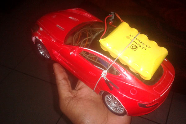
Components
- Arduino UNO
- DC Motors
- Bluetooth module HC-05
- Motor Driver L293D
- 9 Volt Battery and 6 volt battery
- Battery Connector
- Toy Car
Bluetooth controlled car is controlled by using Android mobile phone instead of any other method like buttons, gesture etc. Here only needs to touch button in android phone to control the car in forward, backwardd, left and right directions. So here android phone is used as transmitting device and Bluetooth module placed in car is used as receiver. Android phone will transmit command using its in-built Bluetooth to car so that it can move in the required direction like moving forward, reverse, turning left, turning right and stop.
Bluetooth Module
HC Bluetooth module consists two things one is Bluetooth serial interface module and a Bluetooth adaptor. Bluetooth serial module is used for converting serial port to Bluetooth.
How to operate Bluetooth module?
You can directly use the Bluetooth module after purchasing from market, because there is no need to change any setting of Bluetooth module. Default baud rate of new Bluetooth module is 9600 bps. You just need to connect rx and tx to controller or serial converter and give 5 volt dc regulated power supply to module.
Bluetooth module has two modes one is master mode and second one is slave mode. User can set either mode by using some AT commands. Even user can set module’s setting by using AT command. Here is some commands uses are given:
First of all user need to enter AT mode with 38400 bps baud rate by pressing EN button at Bluetooth module or by giving HIGH level at EN pin. Note: all commands should ends with \r\n (0x0d and 0x0a) or ENTER KEY from keyboard.
After it if you send AT to module then module will respond with OK
AT → Test Command
AT+ROLE=0 → Slave Mode select
AT+ROLE=1 → Master Mode select
AT+NAME=xyz → Set Bluetooth Name
AT+PSWD=xyz → Set Password
AT+UART=<value1>,<value2>,<value3> → set Baud rate
Eg. AT+UART=9600,0,0
Pin Description of accelerometer
- STATE → Open
- Rx → Serial receiving pin
- Tx → Serial transmitting pin
- GND → ground
- Vcc → +5volt dc
- EN → to enter in AT mode
Working Explanation
In this project we have used a toy car for demonstration. Here we have selected a RF toy car with moving left right steering feature. After buying this car we have replaced its RF circuit with our Arduino circuit. This car have two dc motors at its front and rear side. Front side motor is used for giving direction to car means turning left or right side (like real car steering feature). And rear side motor is used for driving the car in forward and backward direction. A Bluetooth module is used to receive command from android phone and Arduino UNO is used for controlling the whole system.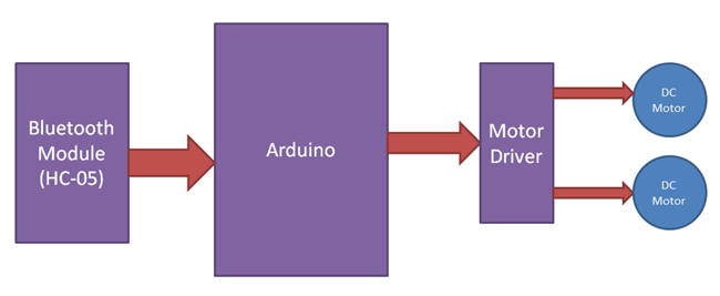
Bluetooth controlled car moves according to button touched in the android Bluetooth mobile app. To run this project first we need to download Bluetooth app form Google play store. We can use any Bluetooth app that supporting or can send data. Here are some apps’ name that might work correctly.
– Bluetooth Spp pro
– Bluetooth controller
After installing app you need to open it and then search Bluetooth device and select desired Bluetooth device. And then configure keys. Here in this project we have used Bluetooth controller app.
- Download and install Bluetooth Controller.
- Turned ON mobile Bluetooth.
- Now open Bluetooth controller app
- Press scan
- Select desired Bluetooth device
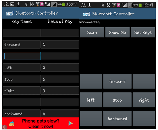
- Now set keys by pressing set buttons on screen. To set keys we need to press ‘set button’ and set key according to picture given below:
After setting keys press ok.

When we touch forward button in Bluetooth controller app then car start moving in forward direction and moving continues forward until next command comes.
When we touch backward button in Bluetooth controller app then car start moving in reverse direction and moving continues reverse until next command comes.
When we touch left button in Bluetooth controller app then car start moving in left direction and moving continues left until next command comes. In this condition front side motor turns front side wheels in left direction and rear motor runs in forward direction.
When we touch right button in Bluetooth controller app then car start moving in right direction and moving continues right until next command comes. In this condition front side motor turns front side wheels in right direction and rear motor runs in forward direction.
And by touching stop button we can stop the car.
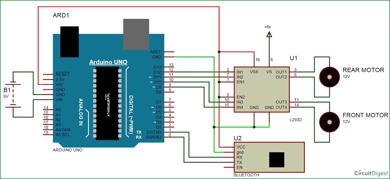
Circuit Diagram and Explanation

Circuit diagram for bluetooth controlled car is shown in above figure. A Motor driver is connected to arduino to run the car. Motor driver’s input pins 2, 7, 10 and 15 are connected to arduino’s digital pin number 12, 11, 10 and 9 respectively.
Read More: Bluetooth Controlled Toy Car using Arduino