Now unfortunately at the beginning of the project i miscalculated my little helicopter’s lift capabilities and so with the equipment fitted it has insufficient power to get more than a couple of inches of the ground, but all of the systems work so this will be more of a theoretical instructable … a tried and tested one 😛
The advantage of this being theoretical though means that it is easier to translate the knowledge for use in other things like cars or planes as opposed to being strictly helicopters.
I would consider the difficulty of this project intermediate to hard depending on how far you want to take it, and would say that experience using an arduino is highly recommended.Finally i would like to say that i am in no way responsible for any damage caused to anything as a result of following this instructable in full or in part. So the Blame is on you if you do something silly!
So without further ado, lets get started!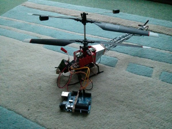
Step 1: Parts
I wanted this to be fairly cheap, the moment you start going towards the £100 mark you might as well get a professional UAV control system, so it is a pretty simple and fairly cheap parts list:
– Arduino (i used an uno, but it is up to you to consider weight and compatibility)
– Programming kit (an arduino needs to be coded for :-P)
– RC Vehicle (there are plenty of them … take your pick)
– Basic Electronics (Wires mainly, i found Male-Female and Male-Male Jumpers very handy)
– Sensors (What is the point of a Man In The Middle System if it wont influence anything)
– Power system (we will discuss this in a later step)
Step 2: The Code Part 1
You can read more about the Library HERE.
The Header and CPP file are attached to this page so just create a file called RCArduinoFastLib in your libraries folder of the arduino IDE and drop these 2 files into it.Note: i did not have the “PinChangeInt” Library installed either so you may need to download and put that in your libraries folder as well in order to successfully compile the Arduino code.
This code example below is the same example as comes with the library, as quite simply i can’t do any better, although later in the instructable you will see the modifications that i have made in order to influence servo positions based on external conditions and to make it more applicable to my use. This example code is just a simple pass through scrip that will change the signals from the receiver in no way at all, allowing us to check the integrity of the circuit that we create and solve issues more easily. It is currently set up to control 3 signal lines (in this called: THROTTLE, STEERING and AUX) so if you require more just add them into the code with the same formatting as is used in the lines for the current signals.
Apologies for the plain text format but i don’t know how to create a code box on here 😛 copy it into the Arduino IDE for easier reading (if anyone comments on how to do this then i will edit it :-P).
Please Remember to read the comments to make it clear as to what the code does
#include <RCArduinoFastLib.h>
// MultiChannels
//
// rcarduino.blogspot.com
//
// A simple approach for reading three RC Channels using pin change interrupts
//
// See related posts –
// http://rcarduino.blogspot.co.uk/2012/01/how-to-read-rc-receiver-with.html
// http://rcarduino.blogspot.co.uk/2012/03/need-more-interrupts-to-read-more.html
// http://rcarduino.blogspot.co.uk/2012/01/can-i-control-more-than-x-servos-with.html
//
// rcarduino.blogspot.com
//
// include the pinchangeint library – see the links in the related topics section above for details
#include <PinChangeInt.h>
// Assign your channel in pins
#define THROTTLE_IN_PIN 5
#define STEERING_IN_PIN 6
#define AUX_IN_PIN 7
// Assign your channel out pins
#define THROTTLE_OUT_PIN 8
#define STEERING_OUT_PIN 9
#define AUX_OUT_PIN 10
// Assign servo indexes
#define SERVO_THROTTLE 0
#define SERVO_STEERING 1
#define SERVO_AUX 2
#define SERVO_FRAME_SPACE 3
// These bit flags are set in bUpdateFlagsShared to indicate which
// channels have new signals
#define THROTTLE_FLAG 1
#define STEERING_FLAG 2
#define AUX_FLAG 4
// holds the update flags defined above
volatile uint8_t bUpdateFlagsShared;
// shared variables are updated by the ISR and read by loop.
// In loop we immediatley take local copies so that the ISR can keep ownership of the
// shared ones. To access these in loop we first turn interrupts off with noInterrupts
// we take a copy to use in loop and the turn interrupts back on as quickly as possible
// this ensures that we are always able to receive new signals
volatile uint16_t unThrottleInShared;
volatile uint16_t unSteeringInShared;
volatile uint16_t unAuxInShared;
// These are used to record the rising edge of a pulse in the calcInput functions
// They do not need to be volatile as they are only used in the ISR. If we wanted
// to refer to these in loop and the ISR then they would need to be declared volatile
uint16_t unThrottleInStart;
uint16_t unSteeringInStart;
uint16_t unAuxInStart;
uint16_t unLastAuxIn = 0;
uint32_t ulVariance = 0;
uint32_t ulGetNextSampleMillis = 0;
uint16_t unMaxDifference = 0;
void setup()
{
Serial.begin(115200);
Serial.println(“multiChannels”);
// attach servo objects, these will generate the correct
// pulses for driving Electronic speed controllers, servos or other devices
// designed to interface directly with RC Receivers
CRCArduinoFastServos::attach(SERVO_THROTTLE,THROTTLE_OUT_PIN);
CRCArduinoFastServos::attach(SERVO_STEERING,STEERING_OUT_PIN);
CRCArduinoFastServos::attach(SERVO_AUX,AUX_OUT_PIN);
// lets set a standard rate of 50 Hz by setting a frame space of 10 * 2000 = 3 Servos + 7 times 2000
CRCArduinoFastServos::setFrameSpaceA(SERVO_FRAME_SPACE,7*2000);
CRCArduinoFastServos::begin();
// using the PinChangeInt library, attach the interrupts used to read the channels
PCintPort::attachInterrupt(THROTTLE_IN_PIN, calcThrottle,CHANGE);
PCintPort::attachInterrupt(STEERING_IN_PIN, calcSteering,CHANGE);
PCintPort::attachInterrupt(AUX_IN_PIN, calcAux,CHANGE);
}
void loop()
{
// create local variables to hold a local copies of the channel inputs
// these are declared static so that thier values will be retained between calls to loop.
static uint16_t unThrottleIn;
static uint16_t unSteeringIn;
static uint16_t unAuxIn;
// local copy of update flags
static uint8_t bUpdateFlags;
// check shared update flags to see if any channels have a new signal
if(bUpdateFlagsShared)
{
noInterrupts(); // turn interrupts off quickly while we take local copies of the shared variables
// take a local copy of which channels were updated in case we need to use this in the rest of loop
bUpdateFlags = bUpdateFlagsShared;
// in the current code, the shared values are always populated
// so we could copy them without testing the flags
// however in the future this could change, so lets
// only copy when the flags tell us we can.
if(bUpdateFlags & THROTTLE_FLAG)
{
unThrottleIn = unThrottleInShared;
}
if(bUpdateFlags & STEERING_FLAG)
{
unSteeringIn = unSteeringInShared;
}
if(bUpdateFlags & AUX_FLAG)
{
unAuxIn = unAuxInShared;
}
// clear shared copy of updated flags as we have already taken the updates
// we still have a local copy if we need to use it in bUpdateFlags
bUpdateFlagsShared = 0;
interrupts(); // we have local copies of the inputs, so now we can turn interrupts back on
// as soon as interrupts are back on, we can no longer use the shared copies, the interrupt
// service routines own these and could update them at any time. During the update, the
// shared copies may contain junk. Luckily we have our local copies to work with 🙂
}
// do any processing from here onwards
// only use the local values unAuxIn, unThrottleIn and unSteeringIn, the shared
// variables unAuxInShared, unThrottleInShared, unSteeringInShared are always owned by
// the interrupt routines and should not be used in loop
// the following code provides simple pass through this is a good initial test
// the Arduino will pass through receiver input as if the Arduino is not there.
// This should be used to confirm the circuit and power
// before attempting any custom processing in a project.
// we are checking to see if the channel value has changed, this is indicated
// by the flags. For the simple pass through we don’t really need this check,
// but for a more complex project where a new signal requires significant processing
// this allows us to only calculate new values when we have new inputs, rather than
// on every cycle.
if(bUpdateFlags & THROTTLE_FLAG)
{
CRCArduinoFastServos::writeMicroseconds(SERVO_THROTTLE,unThrottleIn);
}
if(bUpdateFlags & STEERING_FLAG)
{
CRCArduinoFastServos::writeMicroseconds(SERVO_STEERING,unSteeringIn);
}
if(bUpdateFlags & AUX_FLAG)
{
CRCArduinoFastServos::writeMicroseconds(SERVO_AUX,unAuxIn);
}
bUpdateFlags = 0;
}
// simple interrupt service routine
void calcThrottle()
{
if(PCintPort::pinState)
{
unThrottleInStart = TCNT1;
}
else
{
unThrottleInShared = (TCNT1 – unThrottleInStart)>>1;
bUpdateFlagsShared |= THROTTLE_FLAG;
}
}
void calcSteering()
{
if(PCintPort::pinState)
{
unSteeringInStart = TCNT1;
}
else
{
unSteeringInShared = (TCNT1 – unSteeringInStart)>>1;
bUpdateFlagsShared |= STEERING_FLAG;
}
}
void calcAux()
{
if(PCintPort::pinState)
{
unAuxInStart = TCNT1;
}
else
{
unAuxInShared = (TCNT1 – unAuxInStart)>>1;
bUpdateFlagsShared |= AUX_FLAG; }
}
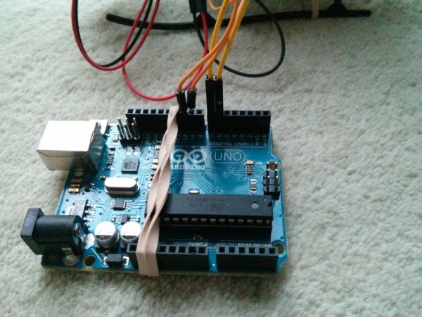
Step 3: Wiring
So once the libraries are installed, the code is compiled and uploaded to your arduino it is time to connect the board to your RC Reciever before proceeding on to test functionality. There are 2 key parts to this step, they are ‘Power’ and ‘Signal’. i shall outline both below:
Signal
This is the most simple of the 2 parts. All you must do is connect the signal line from the RC Reciever to the appropriate pin on the arduino then connect the servo signal line to another pin on the arduino.
In order to know which pins you need to connect to you must consult the following lines of code:
#define THROTTLE_IN_PIN 5
and
#define THROTTLE_OUT_PIN 8
This sets pin numbers that a given servo signal comes in on before being processed and then being sent out on. you can use these pins or you can edit them to use other pins if you wish. Likewise if you add more than just 3 signal lines you will need to define inputs and outputs for those as well. (match the format of what is already there and you will do fine.)
Power
Now this step is highly dependent upon what your setup is, so may need some improvisation on your part. Now i am using a fairly cheap RC helicopter which does not use a standard receiver, furthermore the motors that drive the rotors run off of 3.7V but require a relatively high current. As a result, in my case the only option was to use 2 batteries of appropriate spec; one to power the arduino and the other to power the receiver, servos and motors.
If your RC Vehicle is more professional, with a standard receiver then the receiver will likely run off of a 7.2V battery which would mean that you could add the arduino into the power circuit for the receiver leaving the system as just 1 battery; saving weight. Or possibly 2 if you have a second driving your motors. If you do this though, consider a battery with a higher current rating and capacity but the same voltage to account for the extra load that the arduino puts on the circuit, if you find that the system is stalling when you bring the system up to full speed.
Note: The arduino has a voltage regulator that will correct any variance from the 5V that the chip runs on, to make use of this you must connect the battery terminals to the ‘GND’ and the ‘Vin’ pins on the board or use the barrel plug, DO NOT connect the live wire to the 5V pin!
For more detail: Basics of Turning your Remote Controll Vehicle into an Autonomous System (Drone) Using an Arduino