This is a step by step guide to build an autonomous navigation robot. We use the Arduino microcontroller to control this robot. We have two different programs for this robot. The first enables the robot to drive around and avoid anything that gets in its way. This avoiding obstacles program uses two ultrasonic sensors. Our other program uses 2-D arrays to map out the surrounding area. Based on the values we input into the 2-D array, the robot knows where things around it are. Both programs are included.
Step 1: Materials
We used vex as the frame for our robot, but you can use anything you want to make the structure. In fact, we recommend making the frame from scratch. We also use Vex sensors and vex motors, but even if you use other sensors and motors, (which we recommend that you do) it will work almost exactly the same way.
– (2) ultrasonic sensors (4 for further mapping ability or just to have fun 🙂 )
– (4) servos (5 for funsies)
– Arduino (we used Uno)
– Perf board (we used Radio Shack 276-150: http://www.radioshack.com/product/index.jsp?productId=2102845)
– Lots of Wires
– (2) 9.6 V Batteries (we used Vex batteries: http://www.vexrobotics.com/276-2220.html)
– (1) 9V Battery (to power the Arduino)
– (4) wheels (5” diameter)
– assorted hardware (nuts, bolts, etc.)
– duct tape is also quite helpful
This tutorial has three more steps.
The first section is about the mechanical aspect.
The second section is about the electronic aspect.
The third section is about the programming.
Step 2: Mechanical
First, we need to build a solid base. We have attached pictures here, but you can make it pretty much however you want. We made three different prototypes of this robot. We will discuss the first two here. Mark I had a truck-like shape. It was pretty big, but that also made it slower and harder to turn. Also, for our purposes, the size was pretty much unnecessary. Therefore, in our second model, we made it much smaller and more compact.
Next, we need to add the servos underneath the base so that there is enough space on the outside to attach wheels. We used a four wheel drive. Depending on how strong your servos are, you can use two wheel drive if you want. However, there must be enough space on top of the base to fit the Arduino, PCB, and battery.
Next, add the wheels onto the servos, we added reinforcements outside the wheels to secure the other side of the shaft and keep them from coming off. The two extra wheels at the front are elevated so that if the robot runs into a curb or step, it will be able to climb on top of it. We put duct tape on the back two wheels to reduce the friction so that it turns easier.
Next, we added a battery holder. For us, it was easy to take a Vex battery charger and hack it so that it transmits power to the wheels instead of charging the batteries. Take out the circuit board inside and desolder the positive and negative leads that go to the charging port. Next you solder together the black wires from the two battery terminals and solder together the red wires as well. Next, solder a wire each to the red and black wire. This can plug straight into your PCB. Pictures of this battery holder are under the electronics section.
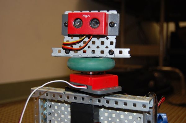
Next, make a mount at the front of the robot for the ultrasonic sensors. If you want to go above and beyond, you can make a mount in the center for a rotating ultrasonic sensor.
We have included pictures of our Mark II design which is a standard four wheel drive as well as our Mark III design which features a crab wheel design. Crab wheel is more complicated to program, but it enables holonomic drive.
Step 3: Electronics
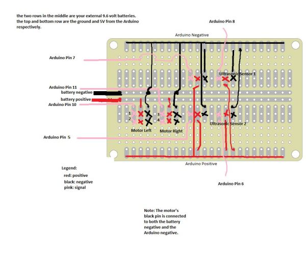
The electronics for this robot are not that hard. If you use the battery holder idea from above, your 9.6 should be connected in parallel. If you aren’t using that idea, connect your batteries in parallel. Then, follow the picture of the circuit board posted here. However, be careful because depending on the size of your base, your servo wires may not be able to reach the circuit board. We are using the same signal wire for servos 1 and 2 and a different signal wire for servos 3 and 4. This is because servos 1 and 2 should always have the same signal while servos 3 and 4 should always have the same signal (because they are on the same side).
If you want to add another sensor or another servo just follow the same pattern as shown in the picture connecting signal to an Arduino pin, 5V to red, and ground to black. Remember that the ground on motors has to be connected to both the Arduino black and the battery black.
We include a rotary encoder on one of our motors just to measure how far it turned. But, this is completely optional.
[box color=”#985D00″ bg=”#FFF8CB” font=”verdana” fontsize=”14 ” radius=”20 ” border=”#985D12″ float=”right” head=”Major Components in Project” headbg=”#FFEB70″ headcolor=”#985D00″]- (2) ultrasonic sensors
– (4) servos (5 for funsies)
– Arduino[/box]
For more detail: Autonomous Autonavigation Robot using Arduino