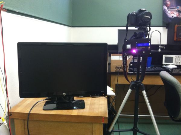
This is a tutorial on how to program your DSLR camera to take photos photobooth-style. It’s a simple Arduino setup that allows you to take continuous photos with 3-second delay intervals. This was built for a college electronics project. A motion sensor detects motion in front of the camera, lights up and shows an LCD that prompts photo-takers to take photos. There are 5 settings in this tutorial – jump shot, single photo, two photos, three photos, and four photos. An HDMI monitor was hooked up in the end to show a live-view screen.
Step 1: Materials and Equipment
Many of these items aren’t required. Mostly the Arduino parts are necessary, but you’ll get to see when we use what as you continue reading.
[box color=”#985D00″ bg=”#FFF8CB” font=”verdana” fontsize=”14 ” radius=”20 ” border=”#985D12″ float=”right” head=”Major Components in Project” headbg=”#FFEB70″ headcolor=”#985D00″]
Electronics, Hardware, and Other Equipment:
— Arduino Uno Microcontroller
— Motion Sensor with PIR (Sparkfun)
— LCD Keypad Shield
— Custom Shield
— Camera (I used a Canon T3i)
— Remote Switch (I used a Canon Remote Switch RS60 E3. Note that this isn’t wireless)
— Resistors: 10K, 220, 220, 100
— Arduino Wall Adapter Power Supply
— Arduino USB Cable (2.0)
— RGB Controllable LED (Common Anode)
— 1N4148 Diode
— Ultra-miniature, Highly Sensitive SPDT Relay for Signal Circuits (G5V-1 Low Signal Relay)
— Wires
— HDMI Monitor
— Mini HDMI to HDMI Cable
— Small Circuit Board
— Box (to contain your setup)
— Screws and standoffs
— Plastic Tie Locks
— Circuit Board Tape
[/box]
Tools:
— Soldering Iron
— Drill Press
— Screw drivers (plus and minus)
— Wire cutters
— Wire strippers
Step 2: Step 1: Setting up the Custom Shield
The shield in the pictures had been customized in our class to suit our needs. It looks slightly complicated, but all you have to pay attention to are these connections:
RGB LED attaches at the left-hand bottom corner. Red hooks to 100 ohms and to pin 13. Greens hooks up to 220 ohms and to pin 11. Green hooks to 220 ohms and pin 10. The data sheet for the LED – RGB Clear Common Anode is provided here:
http://dlnmh9ip6v2uc.cloudfront.net/datasheets/Components/LED/YSL-R596AR3G4B5C-C10.pdf
The 6 screws in the upper left-hand corner corresponds to Term-60, Term-50, Term-40, Term-30, Term-20, Term-10 (from left to right). I’ve only used Term-60 (which is ground and hooks up to pin 9 of the relay), Term-30 (hooks up to Output Signal of motion detector), and Term-20 (hooks up to pin 2 of the relay). We’ll get to relays soon.
The little hole near the RGB LED on the shield (the actual photo) is conveniently connected to 5V of the power of the Arduino.
Look at the 12CA, the two left pins are 5V and ground respectively. These will be used.
Once you’ve got your shield ready, you can connect it to your Arduino.
Step 3: Step 2: Adding your LCD
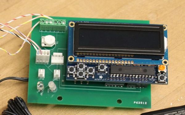
After you’ve connected your custom shield and Arduino Uno, just connect the LCD shield on top of your custom shield as shown in the picture.
Step 4: Step 3: The Motion Sensor
The Sparkfun PIR Motion Sensor has three wires (red, white, and black). Colors vary among motion sensors, but this this is how the connections work here:
Red –> Vcc
White –> Ground
Black –> Output Signal
Vcc and Output Signal were connected with a 10K pullup resistor. To learn more about how this motion sensor works visit this site:
http://bildr.org/2011/06/pir_arduino/
I hooked up the motion detector wires onto a small circuit board, connected the red and black wires with a 10K resistor, and hooked up the red wire to the 5V in the I2CA, the white wire to the Ground in the 12CA of the custom shield, and the black wire to Term-30.
Step 5: Step 4: Camera Remote
Take your wire cutters and snip off the actual remote part of your Canon Remote Switch. Be sure to leave a long enough wire to connect to your camera. You should find three sets of wires. The outside silver wire coating is usually the ground. The other two are Shutter and Focus. You should plug in your cable to your camera and connect each wire to ground individually to figure out which wire is shutter or focus. I stripped the wires such that both Ground and Shutter (white wire) were easily accessible. I’ll be hooking them up on the small circuit board soon.
To learn more about how the camera remote circuit works, check out:
http://www.doc-diy.net/photo/eos_wired_remote/
We will connect the shutter and ground (which makes the camera take a photo) using a relay (this acts as a switch).
For more detail: Automatic Multi-Photo Taker (Photobooth Style)