Winter just arrived. The enemy of all batteries. Last year this was the season the auxiliary battery of my T3 VW camper bus bit the dust. This likely happened because I neglected to take care of it over the winter months during which the bus is typically parked in my garage. When the auxiliary battery is really dead dead, aka croaked, it is not only not working, but it also prevents the main battery used for starting/driving of the bus to be properly charged when driving. Not a good situation if you are somewhere out in the woods and eventually need a ride back to civilization. After almost getting stuck in the boonies, I decided to build a two-channel battery cycle charger that is supposed to keep both batteries happy and healthy for these winter months. You can see this project documented here.
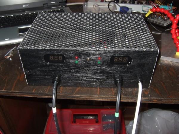
The design, which is housed in perforated aluminum and wood, is based on an ATtiny85 microprocessor. For programming I used an Arduino as ISP and the Arduino programming environment. Connections to the batteries are made with cigarette lighter style connectors. Two analog inputs of the ATtiny85 are used to monitor the voltage of up to two batteries. Two digital outputs are used to switch charging of up to two connected batteries off and on. Two voltmeters display the voltages of the connected batteries and two LED indicators show the charging and connection state of the batteries. The device features a single 15V/5A power supply that, when two batteries are connected, charges either one or the other battery, while ensuring that neither battery drops below a predetermined voltage. Last but not least, there is an on/off switch.
To use the device you plug in one or two batteries and switch it on… in that particular order. The device will then detect any connected batteries, determine their charging state and charge them whenever needed. Keep your batteries plugged in over the winter and you are a happy camper with happy batteries when spring and summer come along.
Please let me know if you have any questions, comments, or suggestions.
P.S. A good complementary device is this battery tester by rlarios which is based on an ATtiny13. Great work rlarios.
Disclaimer:
Please note that lead acid batteries have a number of very significant hazards, including but not limited to electrical hazards, fire hazards, and chemical hazards. You can set a house on fire when charging a lead acid battery improperly. Soldering and dabbling with electronics involves another set of hazards. If you decide to recreate any parts of this instructable, you do it at your own risk. I will not accept any responsibility for your activities, good or bad, and can’t be held accountable for your doings.
Let’s build.
Step 1: Electrical Schematic
When I started with this project, I didn’t know much about lead acid battery chargers and needed to inform myself first to make this project a success. So as usual, I googled until the cables started smoking.
I found many charger circuits that got close to my needs. You can find examples here or on this site. However, none of the devices I found could charge two batteries at the same time.
This charger I found very interesting, since it used a slick design with an IC555 as the main chip. The circuit was built to charge a single battery, using the IC555 as a comparator. Neat. I communicated with the author and started a dialogue on how to build a two battery design. Thanks to the author for his valued responses. Triggered by my questions he posted a blog that had the design I suggested for two batteries with some minor additions.
However, after thinking about it a bit, I concluded that even this design was not suitable for charging two batteries without limiting the charging current to half the current capacity of the power supply. For example, I had a 15 V/5 A power supply which was large enough to charge one battery at a time at 5 A. However, charging two batteries at 5 A would overload the supply. When charging two batteries, the voltage output of my particular supply would break down, the IC555 would lose power and the whole functionality of the device was shot. Not a good enough recipe.
The obvious workaround involved charging the batteries with smaller currents of or below 2.5 A. This would obviously increase the charging time at each battery which was not really that critical for my application since I was going to connect the battery charger for months at a time. To be honest, I had no idea how long the charging times would be. I decided it would be better to use a more intelligent circuit that would, when needed, only charge one battery at a time without letting the other battery drop below its low voltage threshold. In other words, if the low voltage threshold of the second battery is breached while charging the first battery, charging of the first battery is stopped and the second battery is charged instead; or vice versa.
Here I am presenting such a circuit. It uses an ATtiny85 as its brain. This IC is a small microprocessor, that has enough inputs and outputs available for the job and is fully programmable.
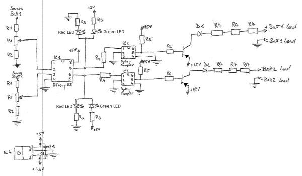
In the figure you see roughly from left to right:
+ Voltage dividers R1, R2, P1, to step down the battery voltages to below 5V levels: 16V => 5V, 1024 steps
+ ATtiny 85, left: analog inputs, right: digital outputs = High / Low = charging / not charging
+ Red and green LEDs with current limiting resistors R3; High signal = red LED on = charging, Low signal = green LED on = not charging
+ Optocoupler circuit: current limiting resistor R4 for internal LED. High signal switches optocoupler on => connection between pin 4 & 5 is created
+ R5 = pull up resistor
=> when optocoupler off, then +15V is at pin 5
=> when optocoupler is on, then GND is at pin 5
+ PNP Darlington transistor with base resistor R6, GND at R6 => Transistor open, +15V at R6 Transistor is closed
+ Reversed current protection diodes D1: Prevents current to flow back from the battery into the circuit.
+ Current limiting resistors R7: These depend on your batteries and power supply. I used 3x 1Ohm/25W resistors to start out. These limit the output current to maximal 5A. Note that the output current is significantly decreased by the internal resistor of the battery you are charging. I decided, since my goal was to maintain the battery charging state over weeks at a time, a high charging current wasn’t quite that important. Please see step 13 for more explanation.
For more detail: ATtiny85 Two-Channel Lead Acid Battery Charger