Hello, in this project I want to show you how to build a multi functional Police Light with a Attiny25/45/85 .
It will have serval animations , which can be changed with a button on the circuit board, it has 2 channels, which can be controlled with PWM. That allows us to add serval animations or police light flashing sequences. The maximum rated current per channel is 500mA, that allowes us to control high power LED´s, LED stripes or old Light Bulbs!
Why did i build this?
Well, my motivation was a colleague of mine is a huge fan of very old toy cars, so he asked me if i can repair a broken police light of one of this cars. As it was a american car so a astable multivibrator wasnt a possibility. That is why i used a Attiny to controll it, that allows us to add serval animations!
Features:
Voltage: 5V
Current(stand by): less then 10mA
Serval animations
2 Channels
Both output channels have PWM
Output Current per channel: 500mA
On/Off button
Animation change button
Small size
Step 1: Materials and tools!
It should cost less then 4$
Materials:
2 Buttons (off/on)
2 Resistors ( 1kOHM )
2 Resistors ( 220kOHM )
2 Resistors ( 450OHM )
2 Diodes ( 1N4007 or Equal )
a Attiny 25/45/85
Some Terminals with screws
a 8 pin IC holder
2 BC548 ( or Equal )
unisolated wire
some solder
a circuit board
For testing:
2 LED´s
Tools:
soldering iron
a forceps
a cutter
Attiny programming:
A attiny programmer
or
a arduino
a breadboard
some wires
a capacitor
or
a arduino
a attiny programming shield
Software:
Arduino ( www.arduino.cc )
You can order the required items on http://de.farnell.com/ , also there you can get more informations about the Arduino board and the Attiny.
Step 2: Circuit board layout
Here is my circuit board layout, it is simple and easy fit on a a small circuit board. It also should be easy to assemble.
The 2 output channels will be on the pins 0 & 1 , this are PWM outputs. The pins 3 & 4 will be input pins for the Buttons
Importand, dont wire the Transistors wrong, it can destroy them!
In the circuit plan i made a mistake, the diodes have to go to GND (0V) not to 5V!!!
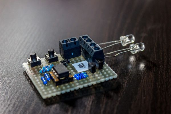
Step 3: Circuit board layout #2
Assembled mine looks like this. There is nothing much to say, its your choice how you like it to look like.
For a single LED we wouldnt need the transistors, but we may want to add more then one LED or we want to add Light bulbs, so the transistors will switch a higher current.
Also you amy want to add stickers, to mark the polarity of the in and outputs and to to add a small description of what it is. 🙂
For more detail: Attiny25/45/85 Police Light, with Arduino!