I just happened to see some large strips of LED lighting when I was picking up some parts at Maplin which were on sale (if I remember correct they were around £12 per approx. 2m strip) however the controller/driver was still around £40, so I thought I would just build a better one myself.
I wanted it to be a web enabled controller as there are a lot of cool things that can be done with a device once it is accessible over HTTP, and I am working on a home automation server project so it would be good to have some devices which I can test this with.
 Anyway, let’s get started, here is a basic parts list, some of the components may change depending on the nature of your lighting installation (i.e. if you are driving more LEDs you may need higher power transistors, etc.):
- Arduino (Duemilanove, Uno, etc., can be done with a Mega but it is overkill)
- Ethernet Shield
- 12v to 5v switchmode DC-DC converters (my LED strips rat at 12v but the Arduino needs 5v and this is more efficient than a linear converter)
- Assorted resistors (for transistor protection, usually around 100-500 ohms)
- NPN transistors (I just used basic NPN transistors as I was only switching around 300mA per channel)
- Push to make button
- Various connectors and cables
- Stripboard (goes by various other names, I used this to make my driver circuit into an Arduino shield)
- Enclosure (optional but recommended)
- Fuse and fuse holder (optional but highly recommended for permanent installations)
- Scrap materials to make any mounting hardware needed (I used HIPS to mount my Arduino in the enclosure)
Tools I used which would help:
- Soldering iron
- Multimeter
- Small flat screwdriver
- Small posi-drive screwdriver
- Laser cutter (drills and a file will suffice if you don’t have access to one)
All the code for this project is available at this GitHub repo.
Step 1: LED Driver Circuit
NOTE: Please read the next two steps before starting any work mentioned here, I had to do some modification to my original shield because of power issues, they are described on the next step.
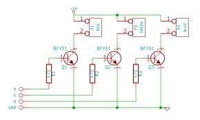
Here you will want to build the driver circuit depicted in the schematic below, this can be done in the same way I did it and made into a shield to stack on top of the Arduino and Ethernet shield, or can be a separate board, either way will work, but I don’t see any advantage to not making it as a shield.
Some minor points, you will want to have three power cables coming from your shield:
- One +12v cable going to the 12v pin on the LED strip output
- One +5v pin going to the 5v pin on the Arduino, and
- One ground going to the ground pin on the Arduino
The reason for this is explained in the next step.
There are some good guides to building a shield from scratch using stripboard on YouTube, alternatively you could use a (semi) pre-built prototyping shield.
Step 2: Circuit Assembly and Testing
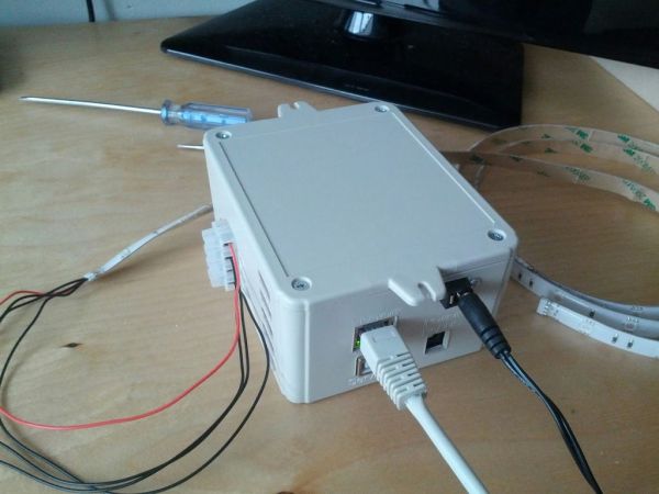
By this time you should have your driver board or shield made, the next step is to test it over a long period of time (a couple of hours in my case) to make sure it is both working properly and efficiently.
I mention efficiency because as you can tell by the image below I am supplying the Arduino with 12v via it’s on board barrel jack and using this to drive the LEDs via the Vin pin on the Arduino, this means that the Arduino must convert 12v to 5v via it’s linear converter, which got very hot after an hour or so.
As a result of this I decided to use a switchmode DC-DC converter to step the 12v down to 5v for the Arduino and supplied it via the 5v pin. completely bypassing the Arduino’s linear converter, to do this I had to modify my shield slightly to redirect the 12v supply for the LEDs and to add cables going to the 5v and ground pins on the Arduino.
The 12v supply for the LEDs will go directly after the main power switch, ground will go to ground and the 5v will be from the output of the DC-DC converter, in my controller I used an isolated DC-DC converter (i.e. the input ground is isolated from the output ground) as I had them left over from audio electronics, however this is not important for this so a regular 3 terminal converter would also be fine.
I also have a push button which toggles the LEDS between off, full on and the last setting set using the web service, once pushed it will change the lights using the last used (or default if not set) transition and transition time. You do not have to use this button, no changes to the code are needed to disable it, if you do want to use it all it has to do is switch an Arduino pin to ground.
Step 3: Arduino Script and Webservices
Now to configure the Arduino script and upload it to your board, there are several important changes that may need to be made:
- Pin constants
On lines 12-15 there are four constants which define the pins to use for the red, green and blue channels as well as the input pin for the quick set button.
The pins for the colour channels must be set to PWM enabled pins, the pin for the button can be anything other than pin 13 (as pin 13 is a pain to use for inputs with a pull up resistor), 0 and 1 (as serial is used for debugging)
If you do not want to use the quick set button then you can leave the default value of 12 (assuming this pin is not used for anything else). - MAC and IP
On lines 42 and 43, set them as suites your network.
Default gateway and subnet mask are obtained through DHCP. - Default transition and transition time
You may want to reset the default transition and transition time that is used after the controller is powered on before it is manually set.
To do this change the constants on lines 34 and 35, a set of valid values for DEFAULT_TRANSITION can be found on lines 24-26.
That should be everything, upload that to your Arduino and give it a test by visiting the web UI in your browser.
The template Arduino script can be found in the GitHub repo.
For more detail: Arduino Web Enabled RGB Lighting