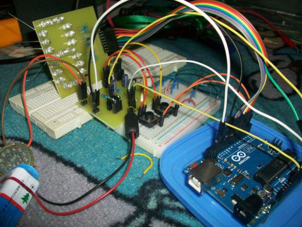
In this instructable, I will show you how to make a simple toy that combination of the LEDs flash and Theremin. We’re gonna using some basic electronics built on top of an Arduino. The basic idea of 7 Segment LED Display was from Enjoying Electronics. The original Enjoying Electronics article is here, you can get more details of explanation about making 7 Segment LED Display there.
The basic idea was to use a LED display programming by Arduino that can display some character with various intensity of flash. Then I saw some Theremin Instructables using Light sensor that made a unique sound when it given the light. Then the idea to combine the both project really made me excited.
This project was made for my own project on campus. It is built since 3 months ago, so there will be some different picture for one part, because it’s been fixed from time to time, and continues to have a progress.
This circuit it’s so simple, but the process requires patience, precision, and efficiency.
This is the video of my Arduino – Theremin with 7 Segment LED Display
(change the quality for a better view)
Step 1: Parts and tools
[box color=”#985D00″ bg=”#FFF8CB” font=”verdana” fontsize=”14 ” radius=”20 ” border=”#985D12″ float=”right” head=”Major Components in Project” headbg=”#FFEB70″ headcolor=”#985D00″]
Here is all you will need:
(1) Arduino UNO R3
(1) 10K potentiometer
(21) LEDs (White, Red, Green, Blue, Yellow)
(2) Push Button
(1) LDR (Light Dependent Photo Resistor)
(1) PCB Matriks / Perfboard
(1) Speaker 8 ohm (0,5 – 0,6 watt)
(2) 10uF Electrolit Capacitors
(3) 10K ohm resistors
(7) 100 ohm resistors
(1) 9V battery
(1) 9V battery box with on-off switch
(1) Potentio knob
(3) Spacer 0,5 cm
(4) Spacer 1 cm
(2) Spacer 2 cm
(1) Project enclosure
– Breadboard
– Shrink tubing
– Jumper wire
– Rainbow wire (optional)
– Male header extended (optional)
– Male header bended (optional)
– Blackhousing / female 1×1 header (optional)
Tools:
– Soldering iron
– Solder
– Hot glue
– Mini drill
– Pliers
– Cutter
– Helping hands (if you don’t have it, you can build it from my helping hands instructable )[/box]
Step 2: Build the LED Display (Prototype)
This step is for Protoboard using. In this step you will need :
– (1) Perfboard (that enough for 21 LEDs)
– (21) LEDs (the colour combination is up to you)
– Jumper Wires
As I already said before, you can go to Enjoying Electronics’s Intructables for more details information, specially for this step.
Each color has a specific wavelength, which can produce varying tones when received by the Theremin. That’s why I use a different color LEDs instead of just use one type of LED colors.
Step 1
Place the LED on perfboard. Each segment will have 3 LEDs wired parallel with each other. Be careful with the negative and positive leads, the positives of these LEDs are all connected together in parallel. (See image 2)
Step 2
All the anodes of one row are connected together. There are 3 LEDs in one row. (See image 1). When you supply voltage to the row, the whole row will lights up.
Step 3
All the grounds will be connected together.
Step 4
Solder a quite long wire to positive lead of each row LEDs. (see image 4)
Step 5
Join all the negative lead of each row with a short wire. And solder once again with long enough wire. There will be 8 wires (7 wires for each row, plus 1 wire for ground) (see image 4)
Step 3: Making the circuit on breadboard
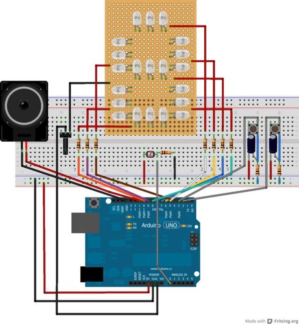
Let’s build it on breadboard first. First, lets put the components on a breadboard so we could see how it worked and how to fit it onto the perfboard. The circuit diagram was made with Fritzing.
Step 1
– Add resistor 100 Ohm for each row
Step 2
– Add resistor 10 K and connect to positive / Vcc, it will be a pull up resistor for push button
– Add a capacitor 10uF, the negative lead connect to ground and connect to one of push button leg. The positive lead connect to other leg of resistor 10K and other leg of push button.
Step 3
– Put LDR series with resistor 10K, the other lead of resistor connect to ground. and the other lead of LDR connect to positive/Vcc.
– Put a jumper between meeting of the LDR and resistor, and connect to the A0 pin of Arduino.
Step 4
– Positive lead of speaker connect to pin 11 of Arduino
– Negative lead of speaker connect to GND of Arduino
Test everything out and make sure that you’re circuit is going to work before you start soldering.
Step 4: Write the code
I’m an Arduino beginner, but this code seems to be pretty good. But I’m not sure to answer your question about advanced programming. And the code that I attach here it’s still for my project on campus, so you will see character “POLBAN” that’s an acronym of my campus name, Bandung Polytechnic State.
You can play with the code for change the characters as you want. So you will have 2 different character display for push the 2 buttons. For the random flash (it’s always looping if you’re not push the push button), you can change the code to get a varying tone, because the distance of row LEDs to the LDR can cause a different tone, and also the color of the LED can affect the tone to be produced.
Note: you are somewhat limited in what letters you can display, such as capital R, Z,W,X, and others.
Step 5: Build 7 Segment LED Display (PCB Printed)
This step is for build on PCB Printed. Because it’s should be done as soon as possible for my project on campus, I’m using a custom PCB (printed circuit board) from a manufacturing company. And it was cheap to get manufactured, the size are about 6 x 6,5 cm.
I’m using Altium Designer to create the PCB design. But you can use other software such Eagle, Protel / Proteus with the schematic that I already attach.
A PCB design for direct toner transfer is added too. The design is slightly different from the prototype shown in the pictures. There are a bit different route around the LEDs, because I can’t find the first design of my PCB on my computer, so I should redesign it.
Step 1
Put the LEDs in order, the combination is up to you, but I like to do the combination as shown on image 3. The reason for the combination is that the green and blue LEDs are not intermingled with each other. I crossed them, and put red and yellow LEDs series with them in a row.
Step 2
Soldering them with carefully.
Step 3
Add resistors to the place. and soldering them with carefully.
Step 4
Soldering 8 male headers (extended) upside down, because we will attach the cables on the back of the PCB. And bend it a little (see image 4). This is for the efficiency.
Step 6: Attach the Cables
Step 1
Create the cables. I’m using rainbow cable, because it’s flexible and easy to remember because there will be one color for each row.
#For the Male side
*This side will connect right to the Arduino
– Strip the end of the cable
– Using a male header (bended)
– Solder it together and put on some shrink tubing / or cover with duct tape (like mine)
– Make 7 of these.
– For the ground I’m using just a male header (extended), you can see on image 1. The green one is for ground.
#For the Female side
*This side will connect to the male header on PCB 7 Segment LED Display. See image 3 to attach the wires in order.
– Using 8 blackhousing / female 1×1 header
Step 2
Connect the cable with the male header on LEDs PCB (see image 3)
– row 1 = brown
– row 2 = red
– row 3 = orange
– row 4 = yellow
– ground = green
– row 5 = blue
– row 6 = purple
– row 7 = grey
Step 3
Test every row with positive leads of the battery / power source 5V, and connect the ground cable to negative leads of power source.
For more detail: Arduino – Theremin with 7 Segment LED Display