I was wondering about on making a sequencer, a big 16 step sequencer was what I wanted to make. To it’s full extension with lots of features including single leds for each step, midi input and output, etc. Then I realised that I should start from a more basic model and then maybe tweak around to see what I can do. So while surfing the web and between other small sequencer projects I found this arduino sequencer, named “arduino punk console” after the simple tone output device from the 555 (atari punk console) and using the arduino as the tone generator.
So here goes a simple project which can later be modified and used in different projects, check last step for more detail on stuff to do with this sequencer.
Schematic, code and original idea is from Beavis Audio, everything can be found at there website:
www.beavisaudio.com
Step 1: Materials
The bill of materials to making this project consists in:
- X8 Momentary pushbuttons, normally open.
- X1 Small Toggle DPDT switch.
- X1 LED, whichever color, it’s only used to indicate that the Arduino is on and working.
- X9 10K resistors.
- X4 100K Potentiometers.
- X1 Female stereo jack, it can be 3,5mm or a 6,3mm.
- X1 Cable.
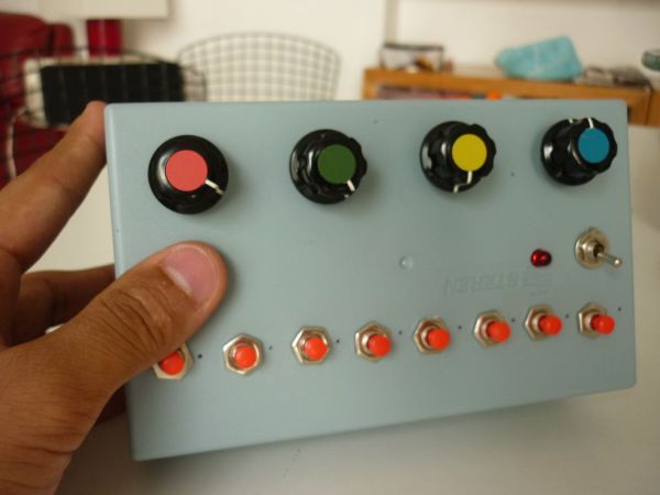
- X1 Enclosure, I just picked up a simple hard plastic box.
- X4 Knobs for the pots, only if you wish so.
List of tools to elaborate:
- Soldering Iron.
- Solder.
- Drill.
- Tweezers.
- Screwdrivers.
Step 2: Schematic and wiring
Following the schematic is fairly easy. What we must notice is that the 10K resistors are pull down, this means it’s hooked up to ground and it holds the logic signal when no other active device is connected. So you must hook the wire leading to the Arduino pins for the steps from the pushbutton. Arduino pins from digital 10 till 2 go to pushbuttons.
Then connect all buttons together with the pots positive lead and hook it up to 5V. All Resistors go together with pots negative leads and hook it up to ground. Also notice the traditional 100K wiring for the volume, which goes to Arduino digital 11. The pots go hooked up to Arduino analog 0, 1 and 3. Finally a red led goes to Arduino pin digital 12.
*There are two schematics. One that I made on Fritzing and the second one which is much better organised, can be found at beavis audio.
Step 3: Code
The original code comes with a LCD setup for displaying frequency changes. I just deleted that part, but you can get the code with lcd setup here.
/* ======================================================================
Arduino Punk Console
A simple programmable 8 step tone sequencer
by dano/beavisaudio.com
Revs
———————————–
15 Sept djh initial version
======================================================================*/
// Map all the input and output pins
#define AnalogInFrequency 1
#define AnalogInTempo 2
#define AnalogInDuration 0
#define DigitalOutSignal 11
#define DigitalInSwitch0 2
#define DigitalInSwitch1 3
#define DigitalInSwitch2 4
#define DigitalInSwitch3 5
#define DigitalInSwitch4 6
#define DigitalInSwitch5 7
#define DigitalInSwitch6 8
#define DigitalInSwitch7 9
#define DigitalInStartStop 10
#define DigitalOutLED 12
// Set up the array for each step
int steps[] = {100,120,140,160,180,200,220,240};
// misc housekeeping
int duration = 50;
int pitchval = 1;
int fPlayMode = true;
int lastPushedStep = -1;
// Initialize the tempo
int tempo = 100;
void setup()
{
// setup pin modes (Digital pins are input by default, but
// I like to set ’em explicitly just so the code is clear.
pinMode (DigitalInSwitch0, INPUT);
pinMode (DigitalInSwitch1, INPUT);
pinMode (DigitalInSwitch2, INPUT);
pinMode (DigitalInSwitch3, INPUT);
pinMode (DigitalInSwitch4, INPUT);
pinMode (DigitalInSwitch5, INPUT);
pinMode (DigitalInSwitch6, INPUT);
pinMode (DigitalInSwitch7, INPUT);
pinMode (DigitalInStartStop, INPUT);
pinMode (DigitalOutSignal, OUTPUT);
pinMode (DigitalOutLED, OUTPUT);
}
[box color=”#985D00″ bg=”#FFF8CB” font=”verdana” fontsize=”14 ” radius=”20 ” border=”#985D12″ float=”right” head=”Major Components in Project” headbg=”#FFEB70″ headcolor=”#985D00″]The bill of materials to making this project consists in:
- X8 Momentary pushbuttons, normally open.
- X1 Small Toggle DPDT switch.
- X1 LED, whichever color, it’s only used to indicate that the Arduino is on and working.
- X9 10K resistors.
- X4 100K Potentiometers.
- X1 Female stereo jack, it can be 3,5mm or a 6,3mm.
- X1 Cable.
- X1 Enclosure, I just picked up a simple hard plastic box.
- X4 Knobs for the pots, only if you wish so.
List of tools to elaborate:
- Soldering Iron.
- Solder.
- Drill.
- Tweezers.
- Screwdrivers.
[/box]
For more detail: Arduino Board Step Sequencer