A medium sized box that requires the user to succeed in a game of hang man in order to gain access to the contents of the box. Great gift Idea!!!
my Arduino sketch will be included in this instructible
sorry for the poor quality pictures!
and keep in mind this is my first instructable,
and I forgot to take pictures of the build in process,
all of these pics are from the completed project.
If you have any questions send me an email and I will get back to you asap, [email protected]
Note:
I “borrowed” a lot of code from Dan Wagoner over at www.nerdybynature.com, you can find his “hangmamduino” project there as well, and Dan Wagoner if you somehow stumble upon this “ible”, thanks for sharing your code, also I would recommend getting a copy of the “truerandom” library and incorporate that into your code as I did, as the native random function is “psuedorandam”.
Step 1: Parts
[box color=”#985D00″ bg=”#FFF8CB” font=”verdana” fontsize=”14 ” radius=”20 ” border=”#985D12″ float=”right” head=”Major Components in Project” headbg=”#FFEB70″ headcolor=”#985D00″]
I am not supplying instruction for the servo lock construction as the parts I used may not be easy to find, its ok just look at the pics below and you will devise something probably a lot better and cleaner 😉
Parts needed:
1 – wooden box
1 – Arduino board with atmega 328
1 – 16×2 LCD display (get a good price at adafruit.com)
2 – 10k potentiometer (if you got your LCD from adafruit it comes with 1 so you only need 1)
1 – knob for potentiometer
2 – normally open momentary contact switch (button)
1 – servo
2 – 10k resistors
1 – speaker
1 – main power switch
1 – LED with built in mount and resistor
2 – plastic project boxes
1 – 9volt battery and battery strap
lots of wire and solder/soldering iron
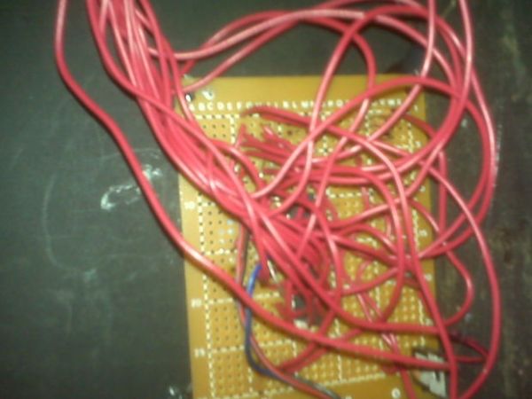
parts to make the mechanical lock(I used random hardware I had laying around, see pic)
hot glue gun
dremel tool and drill
If you are going to take the atmega328 out of the arduino board to use the board with other projects later you will also need:
1 – piece of printed circuit board (PCB) or perf board
1 – atmega328
1 – 28 pin MCU socket
1 – 16mhz crystal
2 – 22pf capacitors
1 – 5 volt regulator
1 – 10nf capacitor
1 – 22uf capacitor (use radial lead not axial lead, non-polarized will not work)[/box]
Step 2: Sketch
Here is the sketch for the Arduino IDE, also included are the “string” and “truerandom” libraries required for this script to work, head over to arduino.cc for instructions on how to install libraries into the IDE.
Step 3: Solder ATmega328 to PCB
follow the instructions on the following instructable (this one is explained better than I could possible try)
http://www.instructables.com/id/Perfboard-Hackduino-Arduino-compatible-circuit/
I will be referring to all pins on the ATmega328 as Arduino pins, I would recommend printing out the atmega328 to arduino pinout map from the above instructable on step 5 picture 2.
also solder a 10k resistor from digital 3 to ground, and another from digital 6 to ground
Step 4: Wiring map for reference
Use this page as reference the wire map is also included in the arduino sketch
ARDUINO PINS:
analog 0 – DO NOT USE!!!
digital 3 – button inside
analog 3 – 10k pot outside
digital 4 – servo
digital 5 – speaker
digital 6 – button outside
digital 7 – LCD D4 11
digital 8 – LCD D5 12
digital 9 – LCD D6 13
digital 10 – LCD D7 14
digital 11 – LCD RW 5
digital 12 – LCD RS 4
OTHER:
LCD 1 – GND
LCD 2 – V+
LCD 3 – Contrast, 10k pot
LCD 15 – V+
LCD 16 – GND
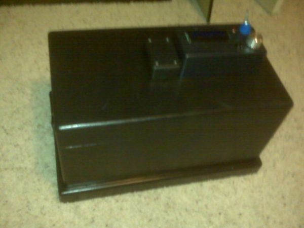
Step 5: Assemble control box and battery box
The battery box is the smaller box to the left of the control box, with the screws facing out so if the 9volt were to drain it could be changed without prying open the box!!!
(hot glue the battery box to the control box, drill a small hole between the 2 boxes for the 2 wires)
sorry for not having detailed pics but I forgot to take some during construction (gimme a break this is my first instructable)
the best way to do this is to cut 14 long pieces of wire (mine were arm length and just barely long enough) and label them on both ends with masking tape and marker as follows:
control box end of wire () ATmega328 end of wire
5v+ () 5v+
5v- () 5v-
9v+ () 9v+
9v- () 9v-
potentiometer () analog 3
button () digital 6
speaker () digital 5
LCD pin 4 () digital 12
LCD pin 5 () digital 11
LCD pin 6 () digital 2
LCD pin 11 () digital 7
LCD pin 12 () digital 8
LCD pin 13 () digital 9
LCD pin 14 () digital 10
install the components in the control box and solder all the labeled wires, solder the 5+ and 5- wires to ALL power and grounds! (+ to pin 2 and 15 on LCD, to one lead on button, one lead on both potentiometers, and pos lead on led, – to neg led lead, neg potentiometer leads, and pin 1 and 16 on LCD) dont forget to solder the smaller 10k pot to the lcd pin 3 for the contrast. Solder the battery strap ground to the 9v- wire, positive from the battery to the main power switch, and from the switch to the 9v+ wire. feed all 14 wires through a hole drilled in the lid of the box, dont screw the control box down yet, we will need to adjust the contrast on the lcd first, I hot glued the contrast pot to the inside of the control box as well as the speaker, and lcd.
For more detail: Arduino powered hangman giftbox/lockbox