Introduction
This is my second article relating to the Arduino Microprocessor Platform. The first one was a simple implementation of the SIMON game using the Arduino. The article can be found here.
For an introduction to the Arduino Hardware, see jeffb42‘s excellent articles, as there is no point in repeating things here.
What Is This Article About?
In this article, I am going to introduce hardware interrupts, and how they can be an important feature of the Arduino Platform.
What is an Interrupt?
Interrupts are a method of signaling to the microprocessor that something has happened. However, you may ask yourself, is that not what happens anyway when you use a digital input, etc.? Well quite simply – No.
When you use the likes of a digital input, you will typically read its value by issuing an instruction, then act on the read value by using some form of logic, i.e. the code is polling for a value.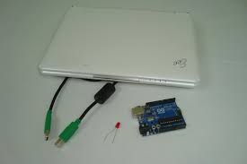 Depending on the complexity of your routines, and the duration of the state change on the input, it is quite possible to not see the change on the input occur at all.
By using an interrupt, the code is literally interrupted, and forced to branch off and do some other execution, i.e. the state change on the input is not ‘missed’. So interrupts are like a hardware trigger.
What Benefit Are They?
Interrupts can help solve timing issues which may occur within your code/hardware setup. You may have had timing issues already and just not understood what happened. How many times have you said to yourself, “Why didn’t that fire?” or “It worked last time I ran it. What is different?”
Getting Down To Business
I am using the Arduino Duemilanove Board for this example, and will be using the Release 18 of the development IDE. This can be downloaded directly from Arduino.cc.
If you are using a different type of Arduino Board, you will need to check out the specs to see which pins are which, as the different types of board can have different allocations and numbers of interrupts/digital pins/analog pins, etc.
On the Duemilanove, there are 2 hardware interrupts available. These are located on Digital Pins 2 and 3. In this demo, we will use Pin 2, and also use Digital Pin 4 as an output to control an LED. The schematic for this is shown below:
Standard Digital Input and Output – No Interrupts
Set up the Arduino as per the schematic and upload the code below to the microprocessor. Here you read the value of an input, do a conditional comparison, run some lengthy routine and repeat.
This will give unpredictable outputs on the LED due to the lengthy process being at an undetermined point in relation to when the input button is triggered. Sometimes the LED will change state immediately, other times nothing happens, and then sometimes you need to hold the button for a while for the state changed to be recognised. [This is code PART A in the downloaded source file.]
int pbIn = 2;          // Digital input on pin 2
int ledOut = 4;        // The output LED pin
int state = LOW;       // The input state

void setup()
{
  // Set up the digital Pin 2 to an Input and Pin 4 to an Output
  pinMode(pbIn, INPUT);
  pinMode(ledOut, OUTPUT);
}

void loop()
{
  state = digitalRead(pbIn);      //Read the button

  digitalWrite(ledOut, state);    //write the LED state

  //Simulate a long running process or complex task
  for (int i = 0; i < 100; i++)
  {
     // do nothing but waste some time
     delay(10);
  }
}
Making Use of Interrupts
We will use the same schematic diagram and modify the code to make use of hardware interrupts. Now when you upload the code, the LED changes state whenever the button is pressed even though the code is still running the same long delay in the main loop. [This is code PART B in the downloaded source file.]
int pbIn = 0;                  // Interrupt 0 is on DIGITAL PIN 2!
int ledOut = 4;                // The output LED pin
volatile int state = LOW;      // The input state toggle

void setup()
{
  // Set up the digital pin 2 to an Interrupt and Pin 4 to an Output
  pinMode(ledOut, OUTPUT);

  //Attach the interrupt to the input pin and monitor for ANY Change
  attachInterrupt(pbIn, stateChange, CHANGE);
}

void loop()
{
  //Simulate a long running process or complex task
  for (int i = 0; i < 100; i++)
  {
    // do nothing but waste some time
    delay(10);
  }
}

void stateChange()
{
  state = !state;
  digitalWrite(ledOut, state);
}
Thevolatilekeyword is added to thestatevariable, this causes the compiler to use RAM instead of a storage register. This is done because the storage register can be temporarily inaccurate if they are being modified by areas other than the main thread. In the Arduino, this relates to code being triggered by interrupts.


The attachInterrupt(param1, param2, param3) requires 3 parameters, these are;
param1= Which interrupt to listen for. This is the Interrupt Number not the Digital In numberparam2= Which code function to call, this must be a method that takes no parameters and returns no value.param3= Which condition to watch for.
The Arduino can listen for 4 types of condition changes. These are:
LOW= The input is at aLOWstateRISING= The input state changes fromLOWtoHIGHFALLING= The input state changes fromHIGHtoLOWCHANGE= The input state changed fromHIGHtoLOWorLOWtoHIGH, i.e. has changed its state
For more detail: Arduino Platform – Interrupts Introduction