The world is going nuts over the Raspberry Pi single-board computer (SBC) for being a whole system under $50. In reality though the Pi isn’t actually the cheapest computing device available. If you want really cheap how does $13.50 sound for a mini computer that can plug into your PC’s USB port be programmed in C++ and let loose into the real world connected to all sorts of crazy stuff? Welcome to the world of the PC-programmable microcontrollers.
So what’s a microcontroller?
CPUs are the show ponies of the computing world – they strut around showing off their high clock speeds but on their own they’re totally useless: they need a whole motherboard’s worth of bits to connect to real-world devices.
On the other hand microcontrollers are compact self-contained bite-size devices that run their own complete computing device – they have storage RAM and interface ports that work with sensors displays and switches. They run everything from fridges to cars and clock radios.
Microcontrollers don’t run anywhere near as fast as CPUs – the ones we’ll look at only clock at 16MHz – but they’re not encumbered by layers of Windows operating system to strangle the life out of them either.
Introducing Arduino
Microcontrollers allow you to create complex gadgets at a fraction of the cost of using individual or discrete integrated circuits. However if you’re going to use microcontrollers a good working knowledge of electronics is required – this series is all about real-world computing in the truest sense.
Yep we’ll talk electronics theory get our inner geek on and look at voltages currents resistors and the like. But frankly I get bored with theory alone damn quick so this series will be all about getting your hands dirty and building stuff. And to do that as quickly as possible we’re going to use the excellent Arduino series of expandable microcontroller boards.
Arduino was created in 2005 by two Italian engineers Massimo Banzi and David Cuartielles with the goal of making it easier for students to learn how to program and grow their understanding of electronics and use it in the real world.
Today 300000 boards later Arduino has grown into a highly expandable system of low-cost microcontroller boards that can be used to build everything from electronic dice to web servers. Arduino boards plug in to your PC via USB and you program them using the free Arduino integrated development environment available from arduino.cc.
Left: Arduino Nano a tiny version of the Uno for one-off projects. Right: A low-cost LCD expansion board that’s easy to program.
What’s inside?
There are several different Arduino boards and many more third-party compatible versions available the most common official ones being the Arduino Uno R3 and the Arduino Nano V3. Both of these run a 16MHz Atmel ATmega328P 8-bit microcontroller with 32KB of flash RAM 14 digital I/O and six analogue I/O. While 32KB doesn’t sound like much we’re not running Windows – you don’t need as much as you think and you can easily add microSD/SD card storage for bigger tasks.
You can buy the Australian-designed Arduino Uno R3-compatible Freetronics Eleven from Jaycar for $40 or pick up Chinese equivalents for under $20 on eBay. For less complex one-off projects eBay has tiny Arduino Nano V3-compatible boards with the same controller USB connectivity and I/O count for just $13.50 including shipping.
OK enough talk – let’s build something!
Hardware: What you’ll need
If you’ve never built anything with electronics before the best way to learn is by doing. Each project we do will have a specific parts list but you’ll also need a basic set of tools you’ll use for everything available from Jaycar Electronics or elsewhere online.
- An Arduino Uno R3 board (eBay $18 or Jaycar XC4210 $39.95)
- An 840-hole breadboard ($19.95 Jaycar PB8814)
- Breadboard jumper kit ($11.95 Jaycar PB8850)
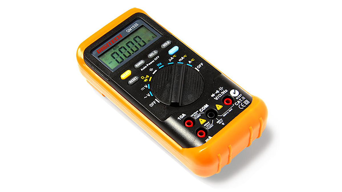
- Auto-ranging digital multimeter ($19.95 Jaycar QM1524)
- A pair of long-nose pliers ($11.95 Jaycar TH1893)
- A pair of side cutters ($11.95 Jaycar TH1890)
For the time being we won’t do any soldering and the only power required will be a USB port or a USB power brick which greatly reduces the chances of you blowing yourself up.
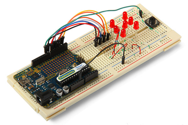
How breadboards work
Most electrical engineers go weak at the knees when they see a breadboard – it’s like a blank canvas to a painter. It’s a reusable plug-in board that lets you create electronic circuits without having to solder. The one we’re using has three sections: two horizontal row sections top and bottom and a main centre section. The holes at the top and bottom are connected horizontally each row separate from the other with a gap between the two halves. The centre section pins are connected vertically in columns separated by the horizontal well in the middle.
Using your multimeter
A digital multimeter (DMM) allows you to measure stuff – electrical voltage across components electrical current through circuits as well as the electrical resistance of components. We recommend an auto-ranging DMM which means all you have to do is simply select volts current or resistance – you don’t have to also select the correct meter range to read the result. DMMs come with leads – the black one plugs into the COM socket and the red one into either the 10A socket or volts/ohms socket as appropriate.
Just quickly the reason for the two sockets for the red lead is because you measure the current through a circuit and the voltagea across or resistance of a component or device. You don’t want the meter to affect the circuit you’re measuring so the 10A current socket has very very low resistance (or impedance) so it doesn’t affect current flow while the volts/ohms socket has a very high impedance so as not to change or load down the component or voltage you’re trying to measure.
And finally never use a multimeter to try to measure the resistance of a component while the circuit is powered up – at best the reading will be wrong and at worst you’ll blow up the meter and/or the component you’re trying to measure. Ideally you want to measure resistance in isolation to everything else.
Measuring resistors
For this project you’ll need seven 680-ohm resistors. Resistors use a special colour code to identify their value displayed by a series of tiny coloured bands on the body. In theory they should be enough to work out the resistor value. The problem is that most resistors now have very thin colour bands and a base background colour that makes them hard to read.
So to be sure measure resistors with your multimeter. Switch the meter to ohms put the red lead into the volts/ohms socket connect one lead to one side of the resistor and the other lead to the other side. Don’t hold the ends of the both leads with your fingers because with higher resistor values your skin’s own resistance will alter the reading.
Any serious geek worth their salt learns the resistor colour code by heart but measuring a resistor is the most reliable way to know its value.
Let’s look at how it all comes together by building our electronic die
For more detail: Arduino Masterclass Part 1: Make your own hardware